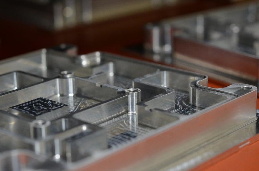
Engineers can spend days or even weeks designing the ideal aluminum RF shield for their application. Fastener placement, wall thickness, cavity location, materials and many other factors are engineered to optimize performance. When Modus Advanced, Inc. began milling RF shields, the company was faced with a question; which of the many choices of measuring equipment is best suited to verify our processes are producing shields that meet customer's specifications and shielding effectiveness needs?
Best Way to Inspect Machined Aluminum RF Shielding Components
There are full-contact machines with probes that physically measure the size, shape and ratio of objects, non-contact machines that use light or lasers to measure objects, and of course machines that use video cameras.
We didn't want to assume a full contact coordinate measuring machine (CMM) was the best for inspecting a milled enclosure, so we formed a small team to study and identify equipment that would accurately and quickly lead to optimal quality assurance. While researching the equipment choices we considered features, ease of programming, speed, and above all, accuracy.

Visit the Complete RF Shielding Resource Center
Comparing Measurements via Probes, Laser Scanners, and Lights
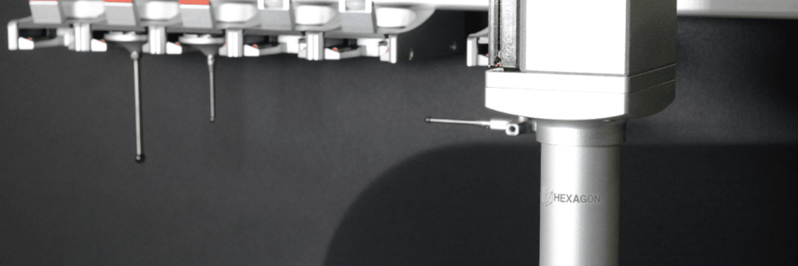
Coordinate Measuring Machines (CMM) are popular and widely used for RF shielding machined parts due to the various features they are capable of measuring.
CMM's are capable of reliably measuring length, inner and outer diameter, step height, hole depth, hole diameter, radii, run out, roundness, and flatness. Most CMM's come with a variety of probes that physically touch the parts to verify features. Optional scanning probes can be added to many CMM's to obtain profile data by dragging across a flat surface to measure distance, flatness, diameters, and more.
Three-dimensional laser scanners play an important role in quality assurance. They create a 3D digital capture of a part by using lasers to scan and measure a part's surface in just a few seconds. They're capable of measuring complex designs and complete profiles, leading to accurate representations of an object's shape.
Passing the scanner over the object's surface collects multiple data points which are then constructed as a point cloud. The 3D laser scanner is available in different types of configurations including stationary, hand-held and can even be mounted on a robotic arm.
Another way to accurately measure parts is a 3D structured light scanner. The scanners use projected light patterns and a camera system to measure a part's features. The device's software then triangulates the data points to create a 3D representation of the part (Motley, D. 2017), similar to the 3D laser scanner.
It's important to note the 3D structured light scanner's we looked at wouldn't accurately measure typical features found on RF shields. Step height, hole depth, hole diameter, roundness and flatness measurements would need to be verified using a different measurement process.
Programming
When you've got a quick turn RF shield order to produce, each step in the process has to be optimized to meet quoted lead times.
Unfortunately, many CMMs require hours of programming to measure the first part off the milling machine. Of course the time required to measure the RF shielding components varies depending on the part's complexity. Once the CMM is programmed though, the automation and ability to efficiently measure subsequent parts makes the CMM a good choice.
The non-contact 3D structured light scanners and 3D laser scanners presented some programming difficulties. These systems rely on a point cloud to extract feature information and data. We thought it could be more challenging to extrapolate measurements from a complex design to create the required inspection file.
Using the original CAD model to compare to the scanned image can effectively overcome this problem, which would be useful on profiles and surface deviations. We found using a scanner to measure distances between features wasn't ideal. (Laser Design, 2018).

Read the Complete RF Shielding Guide
Speed
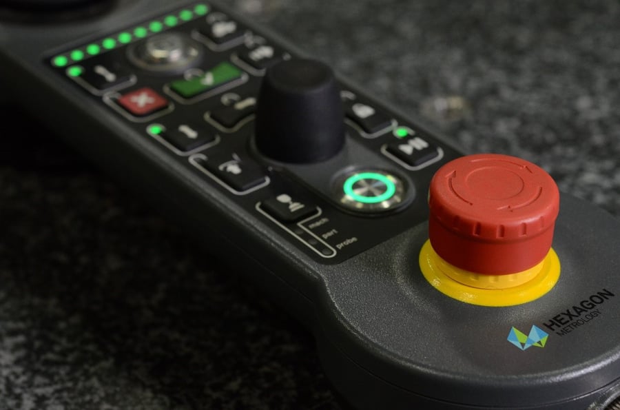
Coordinate measuring machines are notorious for being slow because the touch probe has to drag across the entire surface of the enclosure to capture all of the data points. Fortunately, CMMs offer some convenient features that can help speed up the inspection process, such as probe and stylus racks, high-speed scanning probes, and rotary tables.
Probe and stylus racks can be pre-loaded into a rack on the CMM, which can then be programmed to determine the position of each probe or stylus. High-speed scanning probes allow for quicker scanning of a large surface area. Rotary tables rotate on a single or double axis, decrease the travel distance of the probe, saving much-needed inspection time. Bottom line, even with automation, CMMs are slow!
3D laser scanners can quickly collect data points in a single scan. It may be slower than the 3D structured light, depending on the configurations, but significantly faster than a CMM. A stationary scanner, like the 3D structured light will require a method to either move the part to the scanner for access to each side, or move the scanner itself. A robotic arm or a hand-held scanner will make it much easier to scan any side of the part.
The camera in a 3D structured light scanner can pick up the entire surface instantaneously - just like snapping a picture. Because the camera can only record what's in its immediate view, rotary tables can be extremely useful. By automatically rotating, the camera will pick up different viewpoints, and then merge them all together to define the part in a point cloud.
We found the faster the equipment collects data points on the surface of a part, the less accurate the results. If you're willing to sacrifice accuracy for speed, definitely check into the feasibility of a 3D or laser scanner.
Accuracy
The typical mid-range CMM is capable of a resolution of 2 microns. Higher end versions are more in the 0.5 micron range.
3D laser scanners have a higher accuracy and are capable of a resolution of up to 7 microns.
3D structured scanners, on the other hand, can be sensitive to environmental effects - such as dust - on both the lenses and the part, which will impact the instrument's precision. In fact, the camera and light systems are limited by the resolution of the lens. Depending on the lenses and magnification, these machines typically range from 25 to 50 microns. The camera and light system is limited by resolution of the lens.
Final Thoughts
Although the 3D laser scanner has a number of capabilities and is extremely versatile, we found the probe based CMM was the most appropriate instrument for measuring RF shields. What's exciting is CMMs are evolving with technology and being combined with lasers and other vision systems to further enhance their capabilities and accuracy.
References
Motley, Darryl. (2017, May 30). How Structured-Light 3D Scanners Work. Retrieved from https://gomeasure3d.com
Laser Design. (2018). 3D Scanning Technology-Hard Work That Looks Like Magic. Retrieved from https://www.laserdegin.com/what-is-3d-scanning
