
Key Points
- GD&T (Geometric Dimensioning and Tolerancing) is a standardized symbolic language governed by ASME Y14.5-2018 that defines exact geometric requirements on engineering drawings.
- Ambiguous tolerances don't just cause rework — in medical, aerospace, and defense applications, they can compromise the safety of the people who depend on that hardware.
- GD&T organizes geometric controls into five categories: Form, Orientation, Location, Profile, and Runout.
- Contract manufacturers certified to AS9100 and ISO 9001 must be able to execute GD&T specs precisely — knowing what to look for in a supplier is as important as writing a good drawing.
- GD&T often provides larger usable tolerance zones than coordinate tolerancing, reducing manufacturing cost without sacrificing function.
When a tolerance is ambiguous, someone downstream has to guess. In automotive, a bad guess means a warranty claim. In aerospace, defense, or medical device manufacturing, it can mean something far worse. The drawing you release doesn't just communicate your design — it sets the standard for every part that gets built from it.
That's the real case for GD&T. It's not paperwork. It's the difference between a part that works and one that doesn't — and between a supplier who can execute your intent and one who's interpreting it.
GD&T serves as the universal translator between design intent and manufacturing reality. When properly applied, it eliminates guesswork, reduces manufacturing costs, and ensures consistent part quality across different production facilities worldwide.
Understanding GD&T Fundamentals
Geometric Dimensioning and Tolerancing is a system of symbols, rules, and definitions used to define the exact geometry of parts and assemblies. It goes beyond basic dimensional tolerancing by controlling how features relate to each other in three-dimensional space.
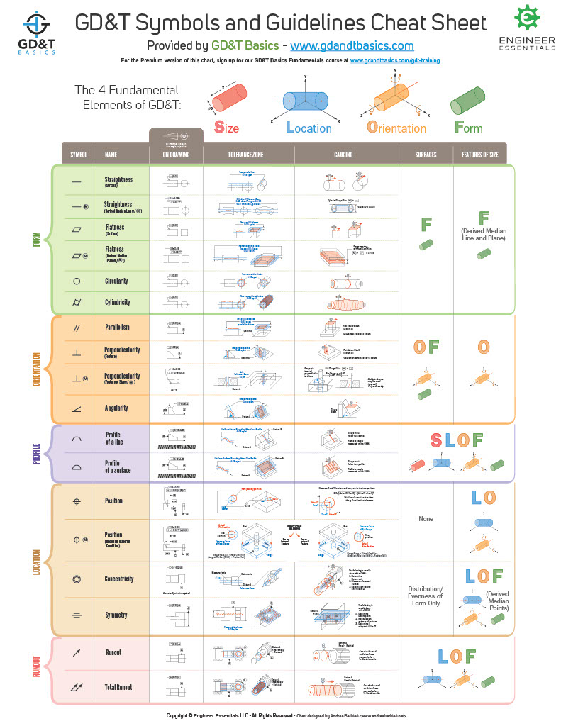
Get a PDF of this wall chart from gdandtbasics.com.
Unlike traditional coordinate tolerancing — which only controls size and location — GD&T addresses five fundamental geometric characteristics that determine how parts function in real-world applications. The system uses datum reference frames, essentially coordinate systems established by physical features on the part, to create consistent measurement standards that manufacturers can replicate regardless of their location or equipment.
The American Society of Mechanical Engineers (ASME) Y14.5-2018 standard governs GD&T implementation in the United States. ISO 1101:2017 provides the international equivalent. Both standards ensure that engineers and manufacturers speak the same geometric language worldwide — and that a drawing released in California means exactly the same thing on a shop floor in Munich.

View the full glossary of terms
Why Use GD&T? Key Benefits for Engineers
GD&T isn't just a drafting convention. It's an engineering tool that pays off across the entire product development lifecycle.
Manufacturing Benefits:
- Tolerance stack-up reduction: GD&T directly controls mating feature relationships, eliminating compounding errors
- Larger usable zones: Circular tolerance zones for position often provide more usable tolerance than rectangular coordinate limits
- Bonus tolerance: Material Condition Modifiers unlock additional tolerance as feature sizes vary
- Streamlined inspection: Clear geometric controls reduce measurement ambiguity and CMM (coordinate measuring machine) programming complexity
Cost Benefits:
- Eliminates unnecessary precision: GD&T forces functional thinking — you only tighten what actually matters
- Reduces rework and scrap: Clearer specs mean fewer parts rejected over specification disputes
- Minimizes interpretation conflicts: Less room for disagreement between design and manufacturing teams
- Optimizes process selection: Suppliers can choose their methods as long as the geometry is met
Quality Benefits:
- Consistent output across suppliers: The same drawing produces the same part regardless of who builds it
- Clear acceptance criteria: Inspection results are unambiguous — a part either falls within the tolerance zone or it doesn't
- Statistical process control: GD&T's precision makes SPC (Statistical Process Control) implementation more meaningful
- Reduced interpretation errors: Symbols communicate geometry; words and notes create ambiguity
The Five Pillars of GD&T Control
GD&T organizes geometric controls into five distinct categories, each addressing specific aspects of part geometry and function. Understanding these categories helps engineers select the right controls for their design requirements.
| Control Category | Primary Function | Key Symbols | Typical Applications |
|---|---|---|---|
| Form | Controls shape of individual features | ⎯ (Straightness), ⬜ (Flatness), ○ (Circularity), ⌭ (Cylindricity) | Surface finish requirements, basic feature shape |
| Orientation | Controls angular relationships | ∥ (Parallelism), ⊥ (Perpendicularity), ∠ (Angularity) | Mating surfaces, assembly alignment |
| Location | Controls feature positioning | ⊕ (Position), ◎ (Concentricity), ≡ (Symmetry) | Hole patterns, critical dimensions |
| Profile | Controls complex surface shapes | ⌒ (Profile of Line), ⌓ (Profile of Surface) | Curved surfaces, complex geometries |
| Runout | Controls rotational variation | ↗ (Circular Runout), ↗↗ (Total Runout) | Rotating assemblies, dynamic parts |
Form Controls: Foundation of Geometric Accuracy
Form controls define the shape of individual features without reference to other features or datums. They ensure that surfaces and features maintain their intended geometry within specified limits.
Key form controls include:
- Straightness: Controls how much a line element can deviate from perfectly straight
- Flatness: Ensures surfaces remain within two parallel planes
- Circularity: Maintains round features within acceptable roundness limits
- Cylindricity: Controls cylindrical features more comprehensively than circularity alone
Form controls typically require the tightest manufacturing precision since they establish the foundation for all other geometric relationships. Apply them strategically — over-specifying form tolerances is one of the fastest ways to drive up machining cost without improving function.
Orientation Controls: Managing Angular Relationships
Orientation controls define how features relate angularly to datum reference frames. These controls ensure that features maintain proper angular relationships regardless of their exact location.
Critical orientation applications include:
- Assembly interfaces: Where parts must mate at specific angles
- Machining setups: Ensuring proper tool access and orientation
- Functional surfaces: Where angular relationships affect performance
- Secondary operations: Maintaining orientation through multiple machining steps
Orientation controls are essential for ensuring proper fit and function in assemblies where angular relationships affect performance — particularly in aerospace and medical device applications where assembly tolerance directly connects to system reliability.
Location Controls: Optimizing Feature Positioning
Location controls govern where features are positioned relative to datum reference frames. These controls are critical for ensuring parts mate correctly in assemblies.
Position tolerance offers several advantages over coordinate tolerancing:
- Tolerance zone flexibility: Circular zones often provide more usable tolerance than rectangular coordinate tolerances
- MMC benefits: Additional tolerance becomes available as feature sizes vary from Maximum Material Condition (MMC)
- Assembly optimization: Direct control of mating feature relationships
- Manufacturing efficiency: Reduces inspection complexity compared to coordinate tolerancing
Location controls often work in conjunction with Material Condition Modifiers to optimize manufacturing tolerance while maintaining functional requirements.
Material Condition Modifiers: Maximizing Manufacturing Flexibility
GD&T incorporates Material Condition Modifiers that allow geometric tolerances to change based on actual feature sizes. This concept provides significant manufacturing benefits while maintaining functional requirements.
| Modifier | Symbol | Definition | Manufacturing Benefit |
|---|---|---|---|
| Maximum Material Condition (MMC) | Ⓜ | Smallest holes, largest pins | Bonus tolerance as features deviate from MMC |
| Least Material Condition (LMC) | Ⓛ | Largest holes, smallest pins | Ensures minimum material for strength |
| Regardless of Feature Size (RFS) | None | Constant tolerance regardless of size | Consistent geometric control |
MMC application benefits:
- Cost reduction: Manufacturers gain flexibility without compromising function
- Faster production: Looser effective tolerances reduce machining time
- Higher yields: More parts pass inspection due to bonus tolerance
- Assembly assurance: Parts always fit together when properly applied
When MMC is applied to position tolerances, manufacturers gain bonus tolerance as feature sizes deviate from MMC toward LMC (Least Material Condition). A hole that measures larger than its minimum size allows the positional tolerance to increase proportionally — manufacturing flexibility without compromising function.
Essential Background Reading:
- Custom Gasket Manufacturing — The Complete Design and Engineering Guide: Foundational guide to gasket design, material selection, and tolerancing for precision applications
- Design for Manufacturability — CNC Machined Metal Parts: How DFM principles interact with GD&T callouts to reduce cost and lead time on machined components
- Manufacturing Traceability for Defense — AS9100, ITAR, and CMMC Documentation: The quality and documentation framework that GD&T-compliant defense parts must operate within
- DFM Guidelines for Aerospace Component Design: How design-for-manufacturability principles apply specifically to aerospace-grade geometric specifications
Datum Reference Frames: Establishing Measurement Consistency
Datum reference frames form the foundation of all GD&T measurements by establishing coordinate systems based on actual part features. These reference frames ensure that all measurements relate to the same geometric foundation, regardless of where or how the part is manufactured.
| Datum Level | Degrees of Freedom Removed | Typical Feature Type | Manufacturing Consideration |
|---|---|---|---|
| Primary | 3 (one plane) | Large, stable surface | Must be accessible for setup |
| Secondary | 2 (perpendicular plane) | Edge or surface | Should be machinable reference |
| Tertiary | 1 (final constraint) | Point or small surface | Often determines part orientation |
Datum selection criteria:
- Functional importance: Choose features that matter for part function
- Manufacturing accessibility: Ensure datums can be easily contacted during setup
- Measurement stability: Select features that provide consistent reference points
- Size and stability: Larger features typically provide better datum references
Poor datum structure compounds measurement errors across large parts — especially when tight tolerances are applied to features far from their controlling datums. Get the datum hierarchy right, and everything downstream gets easier.
GD&T vs. Coordinate Tolerancing: Which Belongs on Your Drawing?
The choice between GD&T and traditional coordinate tolerancing isn't academic. It affects what your part costs, how long it takes to inspect, and whether your supplier interprets your intent correctly.
Coordinate tolerancing defines a feature's location using X, Y, and Z dimensions with plus/minus limits. It's straightforward and familiar, but it creates rectangular tolerance zones — and rectangular zones are geometrically inefficient. A cylindrical hole's true position can fall anywhere within a circular region, but coordinate tolerancing only accepts positions within a square. That mismatch throws away usable tolerance.
GD&T uses circular (or cylindrical) tolerance zones for position, which can provide up to 57% more usable tolerance area than the equivalent coordinate tolerance — without changing the functional requirement at all.
Use coordinate tolerancing when:
- Parts are simple with minimal assembly interaction
- Feature geometry has no angular or form criticality
- The manufacturing process is well-understood and stable
- Documentation simplicity outweighs tolerance optimization
Use GD&T when:
- Parts must assemble with mating components
- Geometric relationships affect function or performance
- Tolerance stack-up is a risk across multiple parts
- Inspection consistency across suppliers is required
- You're working in a regulated industry with quality system traceability requirements
For most precision components in aerospace, defense, or medical device manufacturing, GD&T isn't optional — it's what makes a drawing executable by a supplier who takes quality seriously.
GD&T in Regulated Industries: When Tolerances Become Life-Critical
Most GD&T tutorials are written for machined metal parts in unspecified industries. That's not the world Modus Advanced operates in.
The parts we manufacture support ventilators, surgical instruments, avionics systems, and defense electronics. In those environments, GD&T isn't just good drafting practice — it's how you ensure that the part performing in the field matches the part that passed validation. That distinction matters when failure means a patient, a pilot, or a service member is depending on what you built.
GD&T in Medical Device Manufacturing
Medical device applications demand tight repeatability and complete traceability. A geometric tolerance on a sealing surface isn't a suggestion — it's the boundary between a device that functions correctly and one that leaks, binds, or fails during a procedure.
FDA validation protocols require documented evidence that parts meet specifications consistently across production runs. GD&T provides the framework for that documentation. When your inspection records show every critical feature measured against a clearly defined geometric control, you have defensible evidence of conformance — not just a note that the part "looked good."
GD&T in Aerospace and Defense Manufacturing
Aerospace and defense applications push GD&T to its limits. Weight is a hard constraint. Tolerances on structural components and flight-critical systems routinely approach the boundaries of what manufacturing technology can achieve and measure.
An AS9100-certified manufacturer working to these standards operates a quality management system designed around this level of rigor. The certification isn't a credential for a wall — it's evidence that the quality system, inspection infrastructure, and process controls are built to execute demanding GD&T specifications reliably and traceably. Understanding AS9100, ITAR, and CMMC documentation requirements for defense manufacturing is essential context for any engineer releasing drawings into that supply chain.
GD&T for Non-Metallic and Flexible Components
Here's a gap every other GD&T resource ignores: most of the guidance written for GD&T assumes you're machining metal. But precision die-cut components — EMI (Electromagnetic Interference) shielding gaskets, thermal interface materials, foam seals, and electrical insulation films — also carry GD&T callouts.
Applying GD&T to flexible or compressible materials requires understanding how those materials behave under measurement conditions. A gasket measured under fixture load doesn't look the same as one measured free-state. The GD&T spec needs to reflect that reality, and your contract manufacturer needs to know how to handle it. If they've only ever cut metal, that's a problem worth catching before you release the drawing. Engineers specifying tolerances on custom gasket designs face exactly this challenge, and it's one most GD&T textbooks don't address.
Related Content:
- Form-in-Place Gasketing. Complete Engineering Guide: How GD&T callouts apply to dispensed gasket geometries and what verification looks like in practice
- Custom EPDM Gaskets. Complete Engineering Material Guide: Material behavior considerations that affect how EPDM gasket tolerances should be specified and measured
- Custom Polyurethane Gaskets. Complete Engineering Material Guide: How polyurethane material properties interact with dimensional tolerancing requirements
- How to Build Your Custom RF Shield. Complete Manufacturing Guide: Geometric and tolerance requirements specific to RF shielding enclosures and EMI gasket interfaces
- Silicone vs. Rubber Gaskets, Complete Material Selection Guide: How material choice affects dimensional stability and the GD&T controls you'll need to specify
What Happens When GD&T Goes Wrong at the Supplier Level
Understanding GD&T in theory is one thing. Executing it on a production floor, and catching the problems before they ship, is another.
The most common failure mode isn't a supplier ignoring your tolerances. It's a supplier interpreting them differently than you intended. Datum selection ambiguity, missing material condition callouts, and inconsistent feature control frame structure all create gaps between what the drawing says and what the manufacturer builds.
These gaps cost money. A re-inspection cycle adds days. A rejected lot adds weeks. In a production ramp for a medical device or a defense program with a hard delivery date, those weeks aren't abstract. They're the difference between a program that ships on time and one that doesn't.
What to look for in a contract manufacturer's GD&T capability:
- Engineering team involvement: Can they review your drawing before quoting and flag interpretation issues?
- CMM infrastructure: Do they have the measurement equipment to actually verify the geometric controls you've specified?
- Quality certifications: AS9100 and ISO 9001 certifications signal that quality processes are systematic, not ad hoc
- Process-specific knowledge: Do they understand how their manufacturing process (die cutting, CNC, waterjet) interacts with your GD&T callouts?
- Documentation: Can they provide inspection reports that map back to your specific GD&T controls, not just dimensional measurements?
A supplier who can answer all of those questions confidently is a supplier who will build your part right the first time.
Common GD&T Implementation Challenges and Solutions
Engineers frequently encounter specific challenges when implementing GD&T. Understanding these pitfalls helps create more manufacturable designs while maintaining functional requirements.
Manufacturing Impact Factors
| Challenge Area | Impact on Lead Time | Impact on Cost | Prevention Strategy |
|---|---|---|---|
| Over-tight tolerances | +200. 400% machining time | Significant increase | Specify functional requirements only |
| Poor datum structure | Extended setup/inspection | Measurement complexity | Choose stable, accessible datums |
| Unnecessary precision | Multiple machining passes | Tool wear, cycle time | Match tolerance to function |
| Complex inspection | CMM programming time | Equipment/labor costs | Simplify geometric controls |
Tolerance Stack-Up Solutions
Traditional coordinate tolerancing often creates tolerance stack-up problems where individual part tolerances combine to create assembly issues. GD&T addresses this through several mechanisms.
Stack-up elimination strategies:
- Direct feature control: Position tolerances control mating features directly
- MMC application: Ensures parts always fit regardless of exact locations
- Composite tolerances: Separate pattern and individual feature requirements
- Profile applications: Control complex surfaces without coordinate dependencies
Software Default Traps
Engineers sometimes specify tighter tolerances than functionally necessary, particularly when using default CAD software values. Software defaults often assume cut taps for threaded holes, specifying drill sizes that may not match the manufacturer's preferred roll tap processes.
Common software-related issues:
- Thread specification defaults: May not match manufacturer's preferred tap type
- Standard tolerance blocks: Often tighter than necessary for function
- Geometric tolerance symbols: Default values may exceed manufacturing capabilities
- Drawing annotation styles: May create inspection complexity
The solution is to specify functional requirements, thread class, position, and orientation. While allowing manufacturers flexibility in achieving those requirements through their preferred processes. This principle sits at the core of design for manufacturability for CNC machined metal parts, spec what matters, not what the software defaults to.
Next Steps:
- How to Work with a Custom Gasket Maker. 8 Essential Engineering Tips: Practical guidance for communicating GD&T requirements to a gasket manufacturing partner
- Custom Gasket Manufacturing in Aerospace. Precision for Mission-Critical Applications: How aerospace-grade GD&T specifications translate into gasket manufacturing requirements
- Custom Gasket Manufacturing for Space Applications: Extreme-environment tolerancing demands for space-qualified gasket components
- CMMC Certified Companies. Finding Qualified Defense Contractors: How to vet contract manufacturers for the certifications that back up GD&T execution in defense programs
Manufacturing Impact: Lead Times and Costs
GD&T implementation directly affects manufacturing lead times and costs. Engineers who understand these relationships design parts that are both functional and economical to produce.
Machining Considerations
| Tolerance Range | Machining Impact | Typical Lead Time Effect | Special Requirements |
|---|---|---|---|
| Standard (±0.127 mm / ±0.005") | Normal operations | Baseline | Standard tooling |
| Precision (±0.025 mm / ±0.001") | Multiple passes | +50. 100% | Temperature control |
| Ultra-precision (±0.010 mm / ±0.0004") | Specialized processes | +200. 500% | Stress relief, environmental control |
Critical manufacturing factors:
- Tool selection: Tighter tolerances require specialized cutting tools
- Setup complexity: Precise geometric controls extend machine setup time
- Environmental control: Very tight tolerances may require temperature-controlled environments (±1°C or better in some cases)
- Multiple operations: Achieving precision often requires additional machining passes
Four-tenths (±0.010 mm / ±0.0004") flatness tolerance is an extremely demanding specification that requires specialized processes and environmental controls far beyond typical manufacturing standards.
Inspection Requirements
GD&T specifications directly determine inspection complexity and duration. Aligning on inspection expectations before production starts saves significant time and cost.
Inspection complexity levels:
- Basic dimensional: Calipers, micrometers (minutes per part)
- Geometric tolerances: CMM programming and measurement (hours per part)
- Complex profiles: Advanced CMM programming and surface scanning (extended time)
- 100% inspection: Every part measured rather than statistical sampling
Some customers specify 100% inspection requirements rather than SPC sampling plans, which dramatically increases inspection time and costs. Understanding these implications helps engineers balance functional requirements with manufacturing economics.
Industry-Specific GD&T Applications
Different industries apply GD&T with varying emphasis and requirements based on their specific functional needs and regulatory environments.
| Industry | Primary GD&T Focus | Typical Tolerances | Special Considerations |
|---|---|---|---|
| Aerospace/Defense | Weight optimization, precision | ±0.013, 0.051 mm (±0.0005", 0.002") | Material certificates, traceability |
| Medical Devices | Repeatability, biocompatibility | ±0.025, 0.127 mm (±0.001", 0.005") | FDA validation, enhanced documentation |
| Automotive | High-volume production | ±0.051, 0.254 mm (±0.002", 0.010") | Statistical process control |
| Industrial Equipment | Durability, serviceability | ±0.127, 0.508 mm (±0.005", 0.020") | Cost optimization |
Aerospace and defense applications typically demand the tightest geometric controls due to weight constraints and performance requirements. Space applications often push machining and measurement capabilities to their limits, requiring geometric tolerances that approach the boundaries of manufacturing technology. Component manufacturing for satellite communication systems represents one of the more demanding GD&T environments, where dimensional precision directly affects signal integrity.
Medical device applications focus heavily on repeatability and traceability, often requiring enhanced inspection protocols and documentation systems. These requirements affect manufacturing lead times more through inspection burden than manufacturing complexity.
Industrial applications typically balance functional requirements with manufacturing economics, applying GD&T strategically to control only the geometric characteristics that affect performance.
Best Practices for Effective GD&T Implementation
Successful GD&T implementation requires understanding both the technical aspects of the system and its practical manufacturing implications.
Design Phase Recommendations
Datum selection guidelines:
- Primary datums: Choose large, stable surfaces accessible for measurement and setup
- Functional relevance: Base datums on features that matter for part operation
- Manufacturing reality: Ensure datums can be easily contacted during production
- Consistency: Use the same datum structure across related parts when possible
Tolerance specification strategy:
- Functional analysis: Determine what geometric characteristics actually affect performance
- Manufacturing consultation: Engage manufacturing partners during the design phase
- Material condition optimization: Apply MMC wherever functional requirements permit
- Inspection planning: Consider measurement complexity when specifying controls
Documentation Requirements
Essential drawing elements:
- Clear datum identification: Unambiguous datum feature symbols and callouts
- Complete tolerance specifications: All necessary geometric controls clearly defined
- Material condition symbols: Proper application of MMC, LMC, or RFS as appropriate
- Notes and specifications: Additional requirements not covered by GD&T symbols
Drawing clarity checklist:
- CAD vs. drawing precedence: Clearly specify which takes precedence when discrepancies exist
- Thread specifications: Define functional requirements rather than manufacturing methods
- Surface finish requirements: Coordinate with GD&T controls and manufacturing processes
- Special processes: Identify any required secondary operations or treatments
See It In Action:
- Component Manufacturing for Satellite Communication Systems: Precision engineering for space applications where GD&T compliance directly affects signal performance
- Link 16 System Component Manufacturing. Tactical Data Links: How tight geometric tolerancing requirements are executed for mission-critical defense communication hardware
- Aerospace Components for MILSATCOM. Military Satellite Communications: Custom precision manufacturing for military satellite programs with demanding dimensional requirements
- Custom Part Manufacturing. Engineering Solutions for Space Applications: Real-world examples of creative GD&T-compliant manufacturing for complex space hardware challenges
Advanced GD&T Concepts
Understanding advanced GD&T concepts enables engineers to handle complex design challenges while maintaining manufacturability.
Composite Tolerances
Composite tolerances separate pattern requirements from individual feature requirements, providing manufacturing flexibility while maintaining functional assembly requirements.
Applications include:
- Bolt hole patterns: Control pattern location separately from individual hole positions
- Feature arrays: Manage overall pattern while allowing local variation
- Assembly interfaces: Ensure pattern fits while optimizing individual features
Profile Applications
Profile controls offer strong solutions for complex geometries that coordinate-based form, orientation, and location controls can't adequately handle.
Profile advantages:
- Complex surfaces: A single control defines entire surface geometry
- Flexible application: Can function as form, orientation, or location control
- Manufacturing efficiency: Often easier to measure than multiple discrete controls
- Design intent clarity: Directly controls the actual designed surface
Frequently Asked Questions About GD&T
What does GD&T stand for?
GD&T stands for Geometric Dimensioning and Tolerancing. It is a standardized symbolic language. Governed primarily by ASME Y14.5-2018 in the United States and ISO 1101:2017 internationally. Used to define and communicate engineering tolerances on technical drawings and 3D models.
What is the difference between GD&T and traditional tolerancing?
Traditional tolerancing uses coordinate measurements and plus/minus tolerances, creating rectangular tolerance zones. GD&T uses geometric controls with circular or cylindrical tolerance zones that better reflect functional requirements, often providing larger usable tolerance area while giving manufacturers clearer instructions about what actually matters for assembly and performance.
What are the main GD&T standards?
The two primary GD&T standards are ASME Y14.5-2018 (used in North America) and ISO 1101:2017 (used internationally). While both systems accomplish the same goal, there are meaningful differences in symbols and application rules. Engineers working across both markets should understand where the standards diverge.
When should engineers use GD&T?
GD&T should be used when parts must fit together in assemblies, when geometric relationships affect function, when tolerance stack-up is a risk, or when traditional coordinate tolerancing creates unnecessarily tight or ambiguous requirements. In regulated industries like aerospace, defense, and medical devices, GD&T is effectively required by the quality systems that govern production.
What are the five types of GD&T controls?
The five categories are: Form (straightness, flatness, circularity, cylindricity), Orientation (parallelism, perpendicularity, angularity), Location (position, concentricity, symmetry), Profile (profile of line, profile of surface), and Runout (circular runout, total runout).
How does GD&T reduce manufacturing costs?
GD&T reduces costs by providing larger tolerance zones, eliminating unnecessary precision, preventing tolerance stack-up issues, and allowing manufacturers to use optimal processes while meeting functional requirements. It also reduces inspection disputes by making acceptance criteria unambiguous.
What is Maximum Material Condition (MMC) in GD&T?
Maximum Material Condition (MMC) is a material condition modifier that provides bonus tolerance as feature sizes deviate from their worst-case (maximum material) condition. It gives manufacturers more flexibility while ensuring parts always assemble correctly. A key tool for reducing cost without compromising function.
How do I choose the right datums for GD&T?
Choose datums based on functional requirements, manufacturing accessibility, measurement stability, and assembly considerations. Primary datums should be large, stable surfaces that relate directly to how the part functions and can be reliably contacted during both machining and inspection.
What is a feature control frame in GD&T?
A feature control frame is the rectangular box on an engineering drawing that contains all the GD&T information for a specific feature. Reading left to right, it specifies: the geometric characteristic symbol, the tolerance value (including any diameter or spherical diameter symbol), material condition modifiers, and the applicable datum references. Every GD&T callout is communicated through a feature control frame.
Can GD&T apply to non-metallic or flexible parts?
Yes, and this is an area most GD&T resources ignore entirely. Die-cut gaskets, EMI shielding materials, foam seals, and thermal interface materials all carry GD&T callouts. The challenge is that flexible and compressible materials behave differently under measurement conditions than rigid metal parts. Free-state versus restrained measurement, material compression, and dimensional variation under load all need to be accounted for in both the drawing callout and the inspection method. Form-in-place gasketing adds another layer of complexity, since the gasket geometry is created in-situ and must be verified against the same GD&T controls as any other precision feature.
Mastering the Language of Precision Manufacturing
GD&T represents far more than a collection of symbols and rules. It provides a systematic approach to communicating design intent while optimizing manufacturing processes. Engineers who master GD&T fundamentals create designs that meet functional requirements while minimizing manufacturing costs and lead times.
The key to effective GD&T implementation is understanding that geometric controls should reflect functional requirements. Not arbitrary precision standards, and not CAD software defaults. When properly applied, GD&T transforms engineering drawings from simple dimensional specifications into comprehensive manufacturing instructions that produce consistent, economical parts.
But writing a good GD&T drawing is only half the equation. The other half is a manufacturing partner who can actually execute it. With the engineering depth to flag problems before they reach the floor, the inspection infrastructure to verify every critical control, and the quality certifications to prove it's systematic.
Because a ventilator seal that passes inspection on paper but fails in the field isn't a tolerance problem. It's a partnership problem. Let's solve it before it gets there.
Ready to work with a manufacturing partner who takes GD&T as seriously as you do? Contact Modus Advanced to speak with an engineer about your design today.
