
Form-in-Place (FIP) gaskets are becoming a cost-effective seal of choice for densely populated electronics packaging where isolation and complex cross section patterns are required. Let's examine a couple of considerations inherent in FIP gasketing, starting with some of these more obvious benefits:
- No assembly is needed.
- Superior flexibility is inherent to close any gap.
- It allows for compartmentalized shielding.
- FIP results in very little scrap material.
- Excellent positioning tolerances.
- FIP can replace wire mesh gaskets, molded-in-place or die-cut gaskets.
As with all gaskets used to keep in what you want kept in, and to keep out what you want kept out, the design is always the most integral part of the gasketing phase. This article will streamline the process as we walk through preventing quality issues, considering significant cost reduction, and what you care about most - a quality product delivered on time!

Visit the Modus Form-in-Place Gasket Resource Center
Do I Design For A Groove In My RF Shield?
Grooves are common in the design of parts and are often required for reliable sealing of the two mating pieces. They provide a solid gasket seat and are certainly necessary for O-rings, which may distort without the groove designed to accept the O-ring.
You might have experienced the complication of designing the groove / gasket combination. It's a number's game for sure: internal diameter, internal perimeter, cross-sectional diameter, O-ring or gasket stretch percentage, percentage squeeze, O-Ring or gasket volume, etc.! That's a lot to consider while in the design phase, and then it all must be tested to ensure your calculations are right on!
Turn the spotlight onto FIP gasketing! The good news is, you don’t need a groove!
This is especially beneficial where the seal design is so intricate that applying the seal into a groove requires skilled hands for accurate placement – time and cost. 
Know that the flexibility of FIP gaskets, with its adhesive capability, eliminates the need for a groove in your design. The dispenser simply lays down a bead, wherever you want it, in whatever material you choose, for whatever sealing requirement you have, and that’s all there is to it! Go ahead. Design the most intricate part, with multiple compartments, in a very small and tightly compressed area, and with no grooves needed for reliable sealing.
Is your calculator adding up the cost savings yet?

Material Selection
With advancements in technology, there is now a vast range of materials available for Form-In-Place gaskets with excellent shielding effectiveness, superior adhesion, heat and humidity resistance, and reliability in low compression sets.
Conductive and Non-Conductive Silicone and Flourosilicone compounds are resistant to heat, cold, moisture, UV, ozone, galvanic corrosion, and pressure. Add electrically conductive filler such as silver, copper, nickel, aluminum, ferrite and graphite particles and you now have an excellent seal for EMI/RFI shielding .
Let's focus on Conductive Silicone and why Nickel Graphite versus Silver is something you should know and care about.
Both provide EMI/RFI shielding and can be formulated to provide electrical conductivity and corrosion resistance. But why choose one over the other? The answer to that is cost !
For many years, the filler material of choice for shielding silicones was silver-aluminum, however with the fluctuating price of silver, it just became too expensive to be cost effective. This opened the door to new EMI/RFI shielding elastomers which do not sacrifice shielding, corrosion resistance or physical properties. Nickel graphite filled silicone performs at the shielding levels of silver-aluminum filled products at a fraction of the cost.
If nickel graphite EMI shielding is good enough for the stringent requirements of the U.S. Military, it could also be a solid solution for your design. In addition to it's high performance shielding qualities, nickel graphite has excellent salt spray and corrosion resistance properties. This material is now used in commercial applications such as medical, automotive, and wireless technology and should be considered in your material selection.
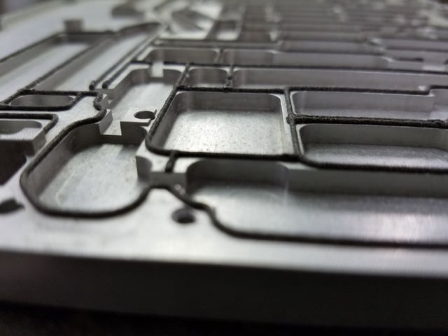
Image: Nickel graphite EMI shielding
Tolerances
As you may expect, tolerances are critical to any good design. With FIP, height is probably the most important physical tolerance specification and it determines gasket width. The height is conditional and depends on the variation in the dimensions of the part and variations in the dispensing parameters. The width is dependent upon the height due to the free forming process and the viscosity of the material. Both height, and consequently width, must be considered in your design.
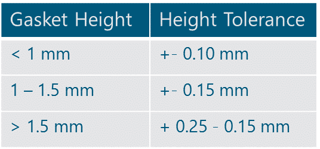
These are suggested specifications and tolerances for your dispensed gasket design:
- Height within tolerance (< 1mm +- 0.10mm, 1-1.5mm +- 0.15mm, >1.5mm +0.25mm -0.15mm)
- Adhesion of the gasket (normally 0.6 N/mm² in shear force)
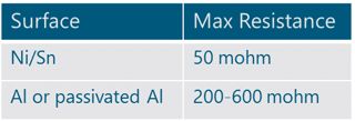
- Resistance (stable resistance is a good indicator of stable process)
- Surface of Ni/Sn should have max resistance of 50 mohm
- Surface of Al or passivated Al should have 200-600 mohm
- Adhesion of the gasket is typically specified as a minimum of 0.6 N/mm² in shear force.
- Specifying resistance maximums is another step to ensure the quality of the production process.
- The electrical resistance that can be measured on the conductive gasket depends on the surface conductivity of the part.

Case Study: Redefining the traditional supplier relationship.
Supply Chain
A shortened supply chain is one of the biggest and most cost-effective benefits of Form-In-Place gaskets. Let’s talk about a “one-stop shop”! How about submitting your order and receiving your part “just in time” and it’s completely ready to go – no gasket inventory to maintain, no assembly required, no reshipment needed to add yet another layer of manufacture? It’s done!
This can and should happen if you choose a Custom Manufacturer which is set up to do it all for you!
- Submit your design.

- Your Custom Manufacturer will precisely mill your parts or have them milled by your preferred machine shop.
- The Form In Place gasket material specified on your design will be meticulously applied to your parts.
- Your parts will be shipped to you on time, with quality control guaranteed by your trusted “one-stop” Custom Manufacturing Partner.
- That’s it!
Is this your current process?
If it’s not, consider the number of times your parts must be shipped from location to location to location before they are complete. How much does this cost in re-packaging and labor? Do you experience Quality Control issues because of part damage caused by too much handling? How much staffing is required to track where all the parts and pieces are in the supply chain today?
If it is your current process, well, you might be way ahead of your competitors in time and cost. When you decide to use a “one-stop shop”, you just might realize you've found the most efficient, cost effective and timely solution to your parts production.
