Form-in-place (FIP) gasket dispensing represents one of the most precise sealing solutions available to engineers today. When properly designed with manufacturability in mind, FIP gaskets deliver exceptional sealing performance while enabling faster production times and lower costs. However, achieving these benefits requires careful consideration of both the metal housing design and the gasket specifications during the design phase.
Why Design for Manufacturability Matters in FIP Dispensing
Form-in-place gasket dispensing represents a critical sealing solution where design decisions directly impact manufacturing feasibility, lead times, and overall project success. Unlike traditional machined gaskets, FIP applications require consideration of both the metal housing design and the dispensing process itself to achieve optimal manufacturability.
Industry-Specific Impacts
Aerospace and Defense: EMI shielding requirements often drive complex gasket path designs that can significantly impact manufacturing complexity. While comprehensive shielding performance remains non-negotiable for mission success, early design optimization can reduce dispensing time from hours to minutes while maintaining electromagnetic protection standards.
Medical Devices: Patient safety depends on reliable sealing performance for life-support equipment and diagnostic devices. Manufacturable FIP designs ensure consistent gasket quality that protects sensitive electronics while enabling faster development cycles that bring critical medical technologies to patients sooner.
The Cascading Effect: A single FIP design decision — such as specifying multiple converging gasket lines in a small area or requiring dispensing in deep, narrow channels — can transform a straightforward 15-minute dispensing operation into a complex multi-hour process requiring specialized needles, custom fixtures, and extensive quality verification.
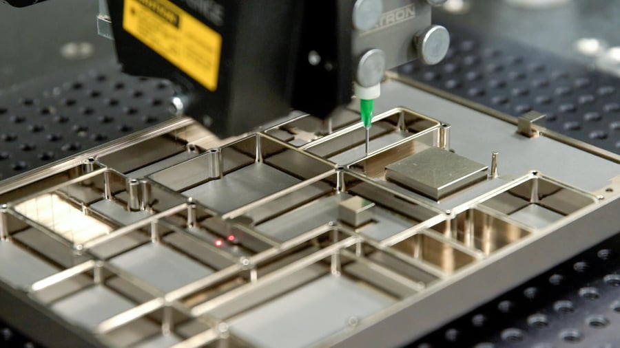
Housing Design Fundamentals for FIP Success
The foundation of effective FIP gasket design lies in creating metal housings that facilitate accurate, consistent dispensing. Housing geometry directly impacts dispensing accuracy, gasket formation, and long-term sealing reliability.
Wall Thickness Requirements
Proper wall thickness prevents gasket overflow and ensures controlled dispensing. The minimum recommended wall thickness is 0.8mm (0.031 inches) for metal housings and 1.5mm (0.059 inches) for plastic housings. These specifications prevent the dispensed material from flowing over thin walls into adjacent cavities, which can cause electrical shorting issues in shielded applications.
Maintaining consistent wall thickness across the dispensing path simplifies programming and improves gasket consistency. Variable wall thickness forces dispensing equipment to constantly adjust flow rates and positioning, increasing both programming complexity and the potential for dimensional variations.
Housing Material | Minimum Wall Thickness | Recommended Thickness | Key Benefits |
Metal | 0.8mm (0.031 inches) | 1.0mm (0.039 inches) or greater | Prevents overflow, easier programming |
Plastic | 1.5mm (0.059 inches) | 2.0mm (0.079 inches) or greater | Accommodates material flexibility |
Compression Stops vs. Groove Design
Design for manufacturability strongly favors compression stops over grooves for FIP applications. Grooves create several manufacturing challenges that impact both quality and lead times. When gasket material is dispensed into a narrow groove, it can contact the groove walls during curing, causing asymmetric gasket formation. This asymmetric curing results in inconsistent compression forces and potentially ineffective sealing.
This approach reduces inspection complexity and improves manufacturing consistency while preventing gasket damage from over-compression.
Surface Finish Considerations
Surface finish quality can significantly affect FIP adhesion characteristics. Extremely smooth surface finishes can create adhesion challenges, requiring additional design considerations to ensure reliable gasket bonding. When surface finishes are too smooth, adding a scribe line along the gasket path can improve adhesion.
A scribe line is a very shallow trace that follows the center line of the gasket path, providing textural features for improved material bonding. This solution prevents gasket delamination issues that can occur during adhesion testing or field service. Surface finish requirements should be specified based on both functional needs and FIP adhesion requirements to avoid redesign cycles.

Read the full Design for Manufacturability guide.
Gasket Path Design and Dispensing Considerations
Effective gasket path design balances sealing requirements with manufacturing feasibility. Complex path geometries and multiple intersections can create dispensing challenges that impact both quality and production efficiency.
Simplifying Path Complexity
Design for manufacturability in FIP applications emphasizes simplifying gasket paths wherever possible. Multiple dispense lines converging in small areas often result in material buildup that creates irregular gasket profiles. Four separate gasket lines starting from a single point may look clean in CAD models but typically merge into an irregular blob during actual dispensing.
When EMI shielding requires multiple sealed compartments, evaluate whether fewer, strategically placed gasket lines can achieve the same isolation performance.
Path simplification reduces both programming complexity and the potential for dispensing errors that require part rework.
Pocket Depth and Dispensing Accessibility
Pocket depth significantly affects dispensing feasibility and manufacturing complexity. Gasket paths located in pockets deeper than 0.25 inches (6.35mm) require extended reach dispensing capabilities that introduce several manufacturing challenges.
Extended reach dispensing necessitates longer dispensing needles, which become more susceptible to clogging when working with particle-filled conductive materials. The combination of small bead sizes and deep pocket dispensing creates the most challenging scenario, particularly with materials containing large metallic particles that can obstruct narrow needle openings.
Clearance between the gasket path and pocket walls becomes critical for extended reach applications. Insufficient clearance can prevent proper needle positioning or cause needle contact with pocket walls during dispensing, leading to dimensional variations or equipment damage.
When deep pocket dispensing cannot be avoided, early manufacturing consultation helps determine tooling requirements and potential process modifications. These applications may require specialized needles, modified dispensing parameters, or alternative fixture designs that can extend lead times and increase manufacturing complexity.
Hardware and Fixture Considerations
Ferrous hardware positioned near some types of gasket paths can disrupt gasket formation during the forming process. Steel dowel pins and other magnetic materials can attract conductive gasket materials, causing dimensional irregularities that affect sealing performance.
When ferrous hardware is required near gasket paths, the manufacturing sequence typically requires installing hardware after gasket dispensing and curing. This sequence change can add 1-2 days to lead times while custom fixtures are created to enable post-gasket hardware installation. Design for manufacturability suggests using non-ferrous hardware near conductive gasket paths whenever functionally acceptable.

Visit the Form-in-Place Gasket Resource Center
Bead Size Specifications and Manufacturing Impact
Bead size selection significantly affects both dispensing feasibility and manufacturing lead times. Understanding manufacturer recommendations and material limitations prevents specification of unachievable dimensions that delay production.
Manufacturer Recommended Bead Sizes
Most engineers reference material supplier documentation when specifying bead dimensions, which typically ensures manufacturable specifications. Material manufacturers like Parker Chomerics, Nolato, and Laird provide detailed technical data sheets that include recommended bead height and width ranges for their specific formulations.
Following these manufacturer recommendations provides the most reliable dispensing results with standard equipment and processes. When engineers specify dimensions within these ranges, manufacturing can proceed with confidence using established dispensing parameters and proven quality control methods.

Read more about Parker Chomerics EMI Shielding FIP Materials
Small Bead Size Challenges
Exceptionally small bead sizes below manufacturer recommendations create significant manufacturing challenges that impact both quality and lead times. Very small beads become difficult to achieve consistently, especially with particle-filled conductive materials where individual filler particles can create surface irregularities relative to the overall bead dimensions.
Additionally, smaller bead sizes than recommended by the manufacturer can change the EMI shielding effectiveness of the gasket. If you require a bead size smaller than manufacturer recommendations, you’ll want to be prepared to test the shielding effectiveness prior to use and make sure it still meets the requirements of your project.
For applications requiring bead heights below 0.003 inches (0.08mm), manufacturing complexity increases substantially:
- Particle visibility becomes more pronounced in grainy materials
- Dispensing consistency becomes more difficult to maintain
- Quality inspection requires specialized measurement techniques
- Extended setup time for equipment calibration
That doesn’t mean these bead sizes aren’t possible! These challenges simply often require custom dispensing trials to determine feasibility before committing to production quantities.

Read an Engineering Case Study on Achieving Small Bead Sizes
Material-Specific Bead Considerations
Different FIP materials exhibit varying behavior at small bead sizes, affecting design for manufacturability decisions. Non-conductive silicone materials typically dispense more consistently at small dimensions compared to highly filled conductive formulations. Materials with large metallic particles present particular challenges when bead dimensions approach particle size.
Material Type | Minimum Practical Bead Height | Manufacturing Considerations |
Non-conductive silicone | 0.002 inches (0.05mm) | Good consistency, standard tooling |
Silver-filled conductive | 0.003 inches (0.08mm) | Particle effects, specialized setup |
Nickel/graphite filled | 0.004 inches (0.10mm) | Larger particles, flow restrictions |
Understanding these material-specific limitations helps engineers make informed decisions about bead size specifications that balance performance requirements with manufacturing feasibility.
Material Selection and Tolerance Specifications
Proper material selection and tolerance specifications ensure reliable manufacturing while maintaining sealing performance. Understanding manufacturer recommendations and industry standards prevents over-specification that increases costs without improving function.
Gasket Dimensional Requirements
FIP gasket tolerances should follow manufacturer specifications to ensure achievable manufacturing targets. Parker Chomerics, for example, recommends ±0.0004 inches (±0.010mm) for gasket height in single-pass applications. Width tolerances typically correlate with height due to material flow characteristics during dispensing.
Extremely tight tolerances below manufacturer recommendations require specialized equipment calibration and extended quality control procedures that significantly impact lead times. The impact of tolerance specifications on manufacturing includes:
Tolerance Type | Standard Specification | Tight Specification | Lead Time Impact |
Height | ±0.0004 inches (±0.010mm) | ±0.0002 inches (±0.005mm) | +25% |
Width | Per height ratio | Custom requirements | +15% |
Position | Standard capability | High precision | +30% |
Custom tolerances should be specified only when functional requirements clearly justify the additional manufacturing complexity.
Material Compatibility
Design for manufacturability requires understanding how different FIP materials behave during dispensing and curing. Particle-filled conductive materials present different dispensing challenges compared to non-conductive elastomers. Highly filled materials with large particles can create flow restrictions in small dispensing needles, particularly in extended reach applications.
Material viscosity also affects flow characteristics and dispensing accuracy, requiring material selection that balances electrical performance with manufacturing feasibility. Early material testing with actual dispensing equipment helps identify potential manufacturing challenges before final design commitment.
Jet Fuel Resistant Material Requirements
Aerospace and defense applications often require specialized FIP materials that can withstand exposure to aviation fuels while maintaining electrical conductivity and sealing performance. Traditional approaches involved dual-bead dispensing — applying separate conductive and chemically resistant gaskets — but modern space constraints in miniaturized avionics systems have made this approach impractical.
Jet fuel resistant sealants must maintain their physical properties and electrical conductivity after prolonged exposure to various aviation fuels including Jet A, JP-5, JP-8, and specialized military formulations. The material must resist swelling, shrinkage, and embrittlement while continuing to provide consistent EMI/RFI shielding effectiveness.
Key performance requirements for jet fuel resistant FIP materials include:
- Superior resistance to common aviation fuels
- Shielding effectiveness >60 dB from 200 MHz to 10 GHz
- Temperature stability from -54°C to +125°C (-65°F to +257°F)
- Low compression set for maintained sealing force
- UL 94 V-0 flammability rating
- Salt fog resistance for maritime aerospace applications
Single-material solutions eliminate the space constraints and manufacturing complexity associated with dual-bead approaches, enabling engineers to design compact electronics enclosures without compromising either EMI protection or chemical resistance. This advancement particularly benefits applications where flange width is limited to 1-2mm (0.039-0.079 inches), making dual-bead designs impossible to implement.
Quality and Inspection Considerations
Quality requirements significantly impact manufacturing lead times and costs. Understanding standard inspection practices versus custom requirements helps optimize design for manufacturability while maintaining necessary quality levels.
Standard vs. Custom Inspection
Standard FIP inspection covers gasket height, width, and basic dimensional conformance using established measurement protocols. Custom inspection requirements for start/stop locations, gap measurements, or specialized dimensional checks require custom programming and extended inspection times.
100% inspection requirements, compared to statistical sampling plans, can dramatically increase manufacturing lead times. These requirements may be necessary for mission-critical applications but should be specified only when truly required:
- Standard sampling plans provide adequate quality control for most applications
- 100% inspection can double or triple inspection time
- Custom dimensional checks require specialized programming
- Start/stop location verification adds significant complexity
Custom inspection requirements should be clearly justified by functional needs rather than applied as default specifications.
Implementation Strategies for Design Success
Successful design for manufacturability in FIP applications requires early collaboration between design and manufacturing teams. Understanding manufacturing capabilities and limitations during the design phase prevents costly redesign cycles and ensures optimal production efficiency.
Early Manufacturing Engagement
Engaging manufacturing partners during initial design development allows for real-time feedback on proposed geometries and specifications. This collaborative approach identifies potential manufacturing challenges before design finalization, reducing development time and ensuring manufacturable designs. Key areas for early discussion include material compatibility, tolerance feasibility, and quality requirements alignment.
Design Documentation Best Practices
Clear documentation prevents manufacturing delays and quality issues. Engineers should specify whether CAD models or drawings take precedence when discrepancies exist. Material specifications should include both base elastomer properties and filler characteristics for conductive applications. Tolerance callouts should reference appropriate standards and include functional justification for tight specifications.
Design for manufacturability in FIP dispensing ultimately balances sealing performance requirements with manufacturing feasibility to deliver cost-effective, reliable solutions that meet demanding application requirements while enabling efficient production.
Frequently Asked Questions About FIP Gasket Design for Manufacturability
What is the minimum wall thickness for FIP gasket housing design?
The minimum recommended wall thickness is 0.8mm (0.031 inches) for metal housings and 1.5mm (0.059 inches) for plastic housings to prevent gasket overflow and ensure proper dispensing control.
Why are compression stops preferred over grooves in FIP applications?
Compression stops prevent asymmetric gasket curing that occurs when dispensed material contacts groove walls, ensuring consistent compression forces and more reliable sealing performance.
What is the maximum pocket depth for standard FIP dispensing?
Gasket paths deeper than 0.25 inches (6.35mm) require specialized extended reach dispensing capabilities that increase manufacturing complexity and lead times.
How do tolerance specifications impact FIP manufacturing lead times?
Tolerances tighter than ±0.0004 inches (±0.010mm) for height can increase lead times by 25% or more due to specialized equipment calibration and extended quality control procedures required.
What surface finish considerations affect FIP gasket adhesion?
Extremely smooth surface finishes may require scribe lines or textural features along the gasket path to ensure proper material bonding and prevent delamination issues.
Partner with Modus Advanced for FIP Design Excellence
When your innovation protects lives or enables mission-critical systems, design for manufacturability becomes essential to your success. Modus Advanced combines deep FIP expertise with vertically integrated manufacturing capabilities, helping you avoid costly redesign cycles while accelerating your path to market.
Our engineering team—more than 10% of our staff—provides real-time DFM feedback during your design phase, ensuring your FIP gaskets are optimized for both performance and production efficiency. From rapid prototyping through production scaling, we handle CNC machining, FIP dispensing, and assembly under one roof, delivering completed parts in half the typical lead time.
Ready to optimize your FIP gasket design for manufacturability? Contact our engineering team for a comprehensive DFM review and quote within 24 hours.
