
Key Points:
- MRL 5–8 alignment is non-negotiable for defense EMI programs: process repeatability, material traceability, and inspection protocol documentation must be established well before production.
- FIP gasket dispensing requires documented process controls: bead geometry tolerances, cure cycle parameters, and start/stop zone management all feed directly into MRL criteria.
- Material qualification is a gate, not a formality: conductive elastomers, RF absorbers, and shielding compounds must be characterized under the environmental conditions your platform will actually see.
- Tolerance stack-up determines shielding effectiveness: Modus holds ±0.127 mm (±0.005") on die-cut parts — tighter than industry standard — and that precision directly affects whether a gasket compresses to spec in the field.
- Vertical integration compresses qualification timelines: a partner who controls dispensing, machining, and assembly under one roof reduces inter-vendor risk, simplifies audit scope, and cuts schedule risk at every MRL gate.
Why Manufacturing Readiness Determines Whether EMI Shielding Actually Works
Defense electronics programs don't fail at the physics. They fail at the transition from prototype to production. EMI shielding and RF components — gaskets, absorbers, shielded enclosures — look straightforward on a drawing. In practice, they're among the most process-sensitive elements in a system.
The scenario program managers actually fear isn't a design that fails on the bench. It's a shielding design that clears development, passes qualification testing, then reveals process-driven variation at production scale — triggering re-qualification runs, compressing program schedules, and eating milestone margin that doesn't exist. That's a manufacturing readiness failure, and it's avoidable.
Manufacturing Readiness Level (MRL) criteria exist precisely because "it worked in the lab" is not a production strategy. For electronic warfare systems, communications equipment, and radar subsystems, shielding performance is a mission-critical requirement. A gasket that doesn't compress consistently, a dispensed bead that drifts 0.20 mm off-path, an absorber bonded with inconsistent adhesive coverage — any of these puts system performance at risk in the field.
MRL assessments for EMI-related components evaluate whether your manufacturing process can reliably reproduce the performance demonstrated in development. That means documented process controls, qualified materials, and inspection methods that catch variation before it ships.

What MRL 5 Through 8 Actually Demands from EMI Programs
MRL gates are qualification milestones. They define whether your manufacturing process can reliably deliver conforming parts under real production conditions — not just whether the design is sound.
For EMI shielding and RF components, the progression from MRL 5 through 8 follows a consistent logic. You're moving from "we understand the process" to "we can execute it repeatedly, at scale, within documented controls."
| MRL Level | What It Requires for EMI / RF Components |
|---|---|
| MRL 5 | Process capability identified; materials selected and characterized; prototype units produced using production-representative processes |
| MRL 6 | Manufacturing process documented; initial process controls defined; prototype-to-production tooling validated |
| MRL 7 | Process capability demonstrated; inspection protocols established and executed; yield data available |
| MRL 8 | Production process in statistical control; all materials and suppliers qualified; inspection methods validated for full production volume |
The jump from MRL 6 to MRL 7 is where most programs run into trouble with EMI components. "We have a documented process" has to become "we have demonstrated yield data." That requires enough production history to show the process is actually in control — not just defined on paper.
The prototyping-to-production transition is where shielding programs most commonly lose schedule. Designs that perform well in development frequently haven't been evaluated for manufacturing repeatability — dispense path optimization, compression stop requirements, and adhesive coverage aren't part of the development conversation until they become a yield problem. Starting that DFM conversation at MRL 5 is the difference between a smooth MRL 7 gate and an expensive re-qualification cycle.
Essential Background Reading:
- Manufacturing Readiness Levels — The Complete Guide: Foundational overview of MRL 1–10 for aerospace and defense engineers, covering criteria, evidence requirements, and program sequencing
- What Are Manufacturing Readiness Levels? MRL 1–10 Explained: Clear breakdown of each MRL level — what it means, what it requires, and how programs advance through the scale
- MRL vs. TRL — Technology and Manufacturing Readiness Compared: Explains how manufacturing readiness levels relate to — and differ from — technology readiness levels in defense program management
- From Breadboard to Full-Rate Production — A Program Manager's MRL Roadmap: Program-level view of the full MRL journey, with decision points and schedule implications at each stage
Compliance Standards Reference: What Every Defense EMI Program Must Satisfy
EMI shielding manufacturing for defense electronics sits at the intersection of multiple compliance frameworks. Each one governs a different aspect of the program — and your manufacturing partner needs to operate within all of them.
| Standard / Certification | What It Governs | Why It Matters for Manufacturing |
|---|---|---|
| MIL-STD-461 | Electromagnetic interference requirements for defense subsystems and equipment | Defines the shielding effectiveness targets your EMI components must meet — the specification your manufacturing process has to reliably hit |
| MIL-DTL-83528 | Conductive elastomeric shielding gasket materials | Specifies material, electrical, and mechanical requirements for gaskets used in defense enclosures |
| AS9100 | Aerospace and defense quality management systems | Requires documented process controls, material traceability, and inspection protocols — maps directly onto MRL advancement criteria |
| ISO 9001 | Quality management system baseline | Foundation for AS9100; required by most defense primes |
| ITAR | International Traffic in Arms Regulations | Registration required to manufacture components for defense programs — a procurement gate, not a background credential |
ITAR registration gets treated as a checkbox in supplier qualification. It isn't. An EMI shielding manufacturer without ITAR registration cannot legally participate in many defense programs — regardless of their technical capability. Verify registration before the qualification process begins, not during source selection.
FIP Gasket Dispensing: Process Repeatability Under MRL Scrutiny
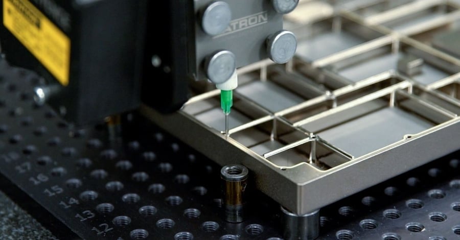
Form-in-place (FIP) gaskets are among the most process-dependent EMI components in a defense electronics assembly. The shielding performance of a dispensed conductive gasket ties directly to bead geometry — height, width, and continuity — which means process variation isn't just a dimensional problem. It's a shielding effectiveness problem.
FIP gasket bead geometry follows specific tolerances that become the foundation of any MRL compliance argument. Standard CHO-FORM bead tolerances run ±0.10 mm (±0.004") on height for beads in the 0.46 mm to 0.86 mm (0.018" to 0.034") range, tightening to ±0.15 mm (±0.006") at larger bead sizes. Start, stop, and T-joint zones carry a wider allowance — those locations require particular attention in your inspection protocol because that's where dispensing variation concentrates.
Tighter tolerances than these are achievable with careful engineering, but they carry real cost and lead time consequences. Specify them only when your design's shielding performance budget genuinely requires it.
For MRL advancement, FIP programs need to demonstrate the following:
- Dispensing path documentation: full CNC path definition, including start/stop locations and T-joint management, locked at MRL 6
- Cure cycle validation: oven temperature profiles, dwell times, and cool-down sequences characterized and documented — Nolato TriShield materials, for example, cure at 150°C (302°F) for 30 minutes
- Bead geometry inspection: 100% or statistically sampled dimensional verification tied to a written inspection plan
- Environmental characterization: shielding effectiveness retention after thermal cycling, humidity exposure, and vibration profiles representative of the deployment environment
The initiation and termination gap specifications for CHO-FORM dispensing — maximum 0.76 mm (0.030") initiation gap and 1.52 mm (0.060") termination gap at wall — aren't just design parameters. Under MRL scrutiny, they're process capability checkpoints your manufacturing partner needs to demonstrate they can hold consistently across a production run.
Dispense path design is a DFM decision, not just a programming task. Minimizing starts, stops, and T-joints reduces the number of process-variation concentrations in your gasket geometry — which directly improves yield and simplifies your inspection burden at MRL 7. That conversation needs to happen before the path is locked, not after the first qualification units reveal problems.
Related Content:
- Custom Gaskets and Sealing Solutions — Process Qualification at Every MRL: Covers how gasket and sealing process qualification maps to MRL requirements across the full program lifecycle
- How Design for Manufacturability Reviews Accelerate MRL Advancement: Explains how DFM reviews at each MRL gate reduce re-qualification risk and compress schedule — directly applicable to FIP gasket programs
- Managing Supply Chain Risk at Each Manufacturing Readiness Level: Addresses how supplier qualification decisions at early MRL gates affect program risk at production scale
- Cost Modeling and Should-Cost Analysis Across MRLs: Covers how manufacturing cost evolves as programs advance through MRL gates — useful context for EMI program budgeting
RF Absorbers: Material Qualification as an MRL Gate
RF absorbers present a different challenge. Where FIP gaskets demand process repeatability, absorbers demand material traceability and environmental qualification. For defense programs — particularly in electronic warfare and radar — absorber materials must maintain their dielectric and magnetic properties across the full operating temperature range of the platform.
Material qualification for RF absorbers starts with characterizing performance across the frequency bands of interest. It extends to adhesive compatibility, outgassing behavior for hermetically sealed assemblies, and retention of properties after thermal aging. These aren't qualification steps you can defer to MRL 7. They need to begin at MRL 5, because a material substitution late in the program is a full re-qualification event.
For programs using converted absorber materials — die-cut sheet stock bonded into enclosures — manufacturing qualification includes both the material properties and the conversion process. Die-cutting tolerances for elastomeric materials depend on material classification and geometry. For sponge or foam absorbers with thickness up to 6.3 mm (0.25") and dimensions between 25.4 mm and 160 mm (1.0" to 6.3"), standard tolerance is ±0.81 mm (±0.032"). Tighter fits are possible but require specific process attention and should be specified only when gap management in the assembly demands it.
Modus holds ±0.127 mm (±0.005") on precision die-cut parts — tighter than industry standard. For EMI absorber applications where gap management is critical to shielding effectiveness, that tolerance capability translates directly into more predictable compression behavior and more consistent performance across a production run.
Next Steps:
- How to Build a Manufacturing Readiness Evidence Package That Passes DoD Review: Step-by-step guidance on assembling the documentation, process records, and inspection data required to clear a formal MRL assessment
- MRL Assessments — What Defense Contractors Need to Know: Covers how DoD MRL assessments are structured, who conducts them, and what reviewers actually look for in supplier documentation
- How Vertical Integration Supports Manufacturing Readiness in Aerospace Programs: Examines how single-source manufacturing partners reduce audit complexity and inter-vendor variation risk at MRL gates
- MRL 4 to MRL 6 — Closing the Gap Between Prototype and Pilot Production: Detailed guidance on the prototype-to-production transition where EMI shielding programs most commonly encounter schedule risk
Conductive Gaskets and Shielding Effectiveness: Connecting Process to Performance
Shielding effectiveness is the output that MRL reviewers ultimately care about. The process controls — bead geometry, material qualification, cure cycles — exist because they're the variables that determine whether the gasket performs. Connecting them explicitly in your manufacturing documentation is what advances an MRL assessment.
For conductive silicone formulations, the relationship between compression and shielding effectiveness is well established. Nolato TriShield 8800 uses Ag/Ni filler and targets 10–50% compression for performance. Volume resistivity, as-molded, runs at 15 mOhm·cm, with average shielding effectiveness of 107 dB across 0.3–9 GHz on Ni/Sn plated aluminum. Those numbers assume the gasket is dispensed correctly and compressed to spec.
That 107 dB figure isn't abstract. It's the shielding margin that keeps a radar system from leaking RF energy an adversary can detect. It's the isolation that protects a communications subsystem from jamming. That's not just a spec — that's a mission outcome.
This is where MRL documentation and real engineering intersect. A shielding effectiveness requirement of 107 dB doesn't mean much if the manufacturing process can't guarantee that the gasket geometry enabling that performance is repeatable. Your MRL evidence package needs to show the chain: material properties → process controls → inspection protocol → performance verification.
For MRL 8, that chain needs to be statistically validated. Yield data, process capability indices, and inspection records aren't bureaucratic overhead — they're the evidence that the chain holds.

Selecting a Defense EMI Shielding Manufacturing Partner: What Actually Matters
Supplier selection for defense EMI programs isn't a price-and-lead-time decision. It's a program risk decision. The wrong partner — one without the certifications, process documentation, or engineering depth to support MRL advancement — can cost a program months at the worst possible time.
Here's what to evaluate:
| Qualification Criterion | Why It Matters | What to Verify |
|---|---|---|
| AS9100 certification | Maps directly onto MRL documentation requirements | Current certificate, scope of registration |
| ITAR registration | Legal requirement for defense program participation | Active registration; verify before source selection |
| Engineering staff depth | DFM input, process optimization, MRL documentation support | Engineers embedded in quoting, quality, and production — not just a department |
| Vertical integration | Single quality system, single audit scope, reduced FOD risk | In-house machining, dispensing, die-cutting, and assembly |
| Tolerance capability | Determines what designs are actually manufacturable | Specific documented tolerances — not a generic capability statement |
| Process documentation maturity | Determines how quickly MRL gates can be satisfied | Existing process control documentation, SPC capability, inspection protocols |
| Material qualification breadth | Broader qualified material library means fewer re-qualification events | Qualified materials list, existing lot traceability systems |
Vertical integration deserves particular attention. A manufacturer who controls dispensing, machining, die-cutting, and assembly under one roof doesn't just offer convenience — they offer program risk reduction. Inter-vendor handoffs introduce variation, create audit complexity, and fragment accountability. On a defense program with schedule pressure and MRL milestones, single-source vertical integration is a risk mitigation strategy, full stop.
See It In Action:
- EMI Shielding and RF Components — Meeting MRL Requirements for Defense Electronics: Application-specific overview of how MRL requirements apply to shielding gaskets, absorbers, and RF enclosures across defense programs
- MRL Frameworks Applied to Medical Device Development: Shows how the same MRL discipline used in defense EMI programs applies to FDA-regulated medical device manufacturing — useful for dual-use programs
- What Is MRL 7? Requirements, Evidence, and Common Pitfalls: Deep-dive on the MRL 7 gate — the milestone where most EMI shielding programs encounter yield and documentation problems
Building an Inspection Protocol That Satisfies MRL Requirements
Inspection protocol design gets treated as a late-stage task. For EMI shielding components on defense programs, it needs to be an early one. The inspection methods you establish at MRL 6 generate the data you need to claim MRL 7 and 8.
An effective inspection protocol for FIP gaskets and RF components in a defense context covers at least three levels:
- In-process dimensional inspection: bead height and width verification at defined sample intervals, with documented acceptance criteria tied directly to the drawing tolerances
- Material verification: lot traceability for conductive compounds, cure cycle records for every production run, and certificate of conformance requirements for all raw materials
- Performance verification: shielding effectiveness testing at defined intervals — frequency, sample size, and acceptance criteria must be specified before production starts, not derived from what testing happened to be performed
The specific inspection frequency and statistical methods should be developed in collaboration with your quality engineering team and your manufacturing partner. What matters from an MRL standpoint is that the protocol exists, is documented, and is being executed — not just planned.
What Modus Brings to Defense EMI Programs
Defense EMI programs need a manufacturing partner who understands that process documentation isn't separate from manufacturing capability — it is manufacturing capability. At Modus Advanced, engineers make up more than 10% of our staff, embedded across quoting, quality, and production. When an MRL assessment asks for process capability data, we have it. When a design needs DFM input on gasket path optimization or absorber stack-up, we provide it before the first part is cut.
Our vertical integration covers the full scope of EMI shielding manufacturing: CNC-machined metal enclosures, FIP gasket dispensing with CHO-FORM and Nolato TriShield materials, die-cut RF absorbers and thermal interface materials held to ±0.127 mm (±0.005") — tighter than industry standard — and final assembly. Everything under one roof means one quality system, one set of process records, and one audit scope. On a program with MRL milestones and schedule pressure, that's a risk management decision, not a convenience feature.
We hold AS9100 and ISO 9001 certifications and operate under ITAR registration — the baseline for defense program participation. More importantly, we understand what MRL advancement actually requires and have structured our processes to support it.
A service member relying on electronic warfare equipment in a contested environment doesn't know who made the gasket. They just need it to work. That's the standard we hold ourselves to. Because failure isn't an option here.
Let's solve this together — contact Modus Advanced to discuss your EMI shielding program requirements.