Sometimes, engineers and designers need machined parts cut and ready to go as fast as possible. Even at top speed, the goal is minimal cost for production without sacrificing quality. At Modus Advanced, Inc., we understand those CNC machining needs. Our goal is to produce world-class machined parts as quickly and affordably as possible every day.
Designers can help us further this goal while saving yourself some money and time in the process, thus leads us into our design rules for CNC machining series. If you implement these 13 design considerations for machined parts, you can reduce your lead time and costs for them. To discuss your unique needs with Modus Advanced, contact us today .
-- Article Continues Below --

Read Everything You Need To Know About CNC Machining
The information below is taken from a webinar hosted by Brian Beck, our Director of Engineering. You can watch the full webinar or read on for more information about how to reduce lead times and manufacturing costs for your CNC machining project and machined parts.
WATCH THE FULL WEBINARGo for Large Inside Corner Radii
Another design consideration for CNC machining is to keep in mind that inside corners are difficult to machine square. CNC machines commonly use a cylindrical cutting tool. Sharp inside corners can add a lot of lead time because they may require electrical discharge machining (EDM). EDM and specialized tools that create sharp inside corners also add to your total cost.
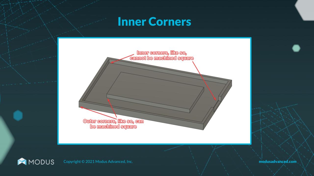
In general, the larger the inside corner radius, the better for your lead time. Larger inside corner radii allow for a larger-diameter tool that can run faster, reducing both cost and lead time.
Don’t Make Pockets Too Deep
Deep pockets aren't necessarily a good thing when it comes to machined parts. A deep pocket is considered to be six times the tool diameter and can impact tool access. The deeper the pocket in your design, the longer the cutting tool to cut the inside corners of that pocket will need to be. A smaller corner radius inside the pocket will call for a smaller, more specialized cutting tool to create those inside corners.
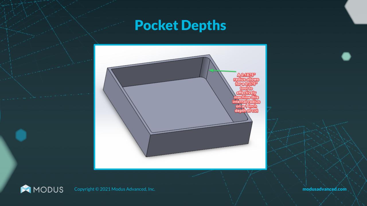
To reduce lead time and costs for your machined parts, keep your pocket depths to around three times the depth of the tool diameter to simplify tool access. When possible, keep inside corner radii as large as you can to allow for a faster run with the tool. Smaller is always possible, but it costs you cycle time and actual costs for the part itself.
Pay Attention to Pre-Drill Tapping Depth
The drilling depths in your design for CNC machining must be deeper than the tapping depths. When you're designing, keep in mind that every tap on the market has a certain amount of thread lead-in :
- Bottoming tap: 1 to 1.5 thread lead-in
- Plug tap: 3 to 5 thread lead-in
- Taper tap: 8 to 10 thread lead-in
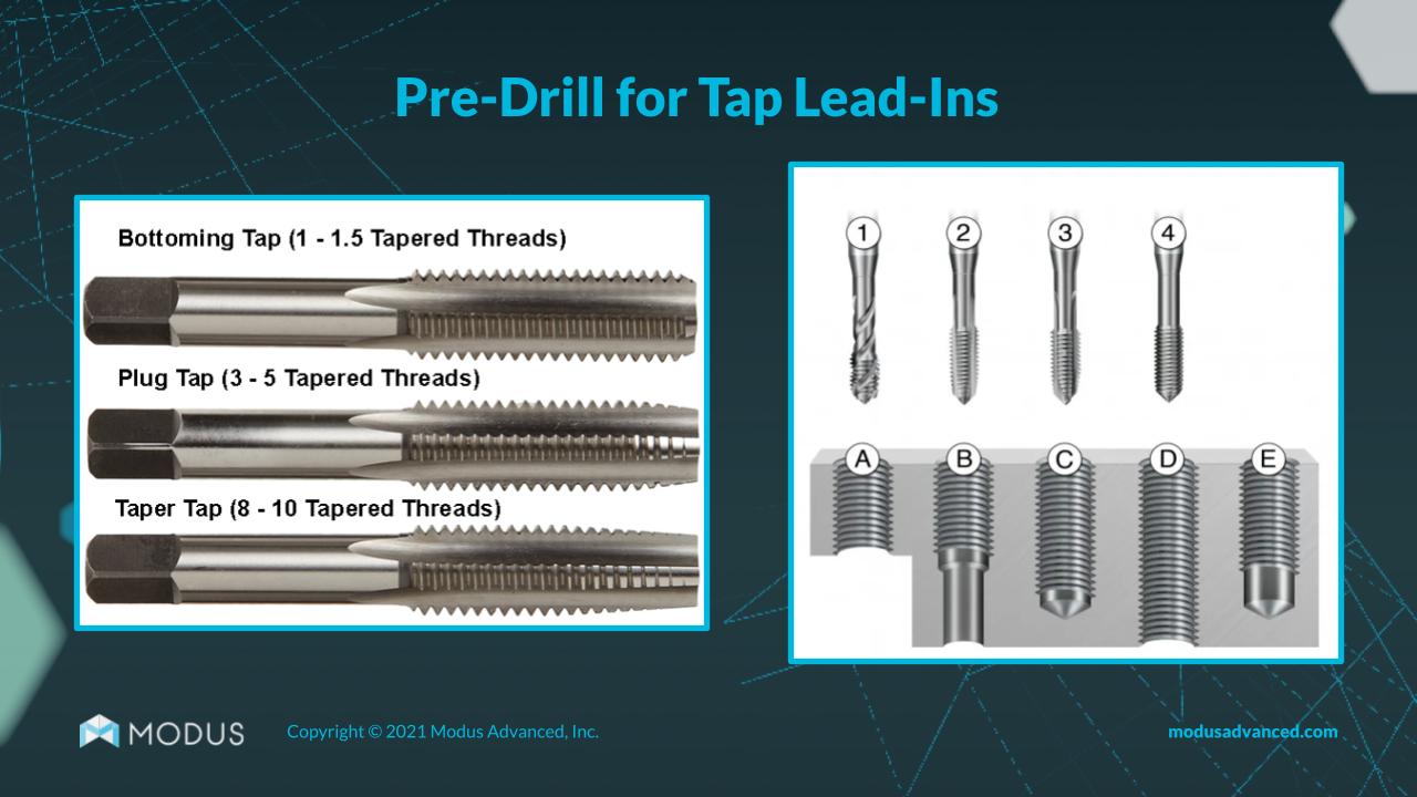
You can avoid production hangups by ensuring that you’ve allowed for enough tapping depth and the drill depth necessary to produce full threads to the required thread depth.
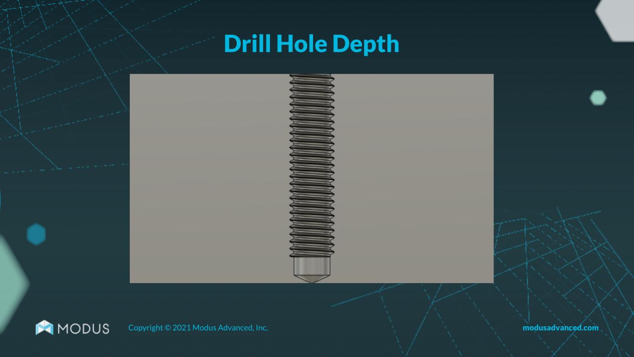
If you are having trouble accommodating the necessary depth, consider making it a through-hole that allows us to drill straight through. This saves on time and cost.
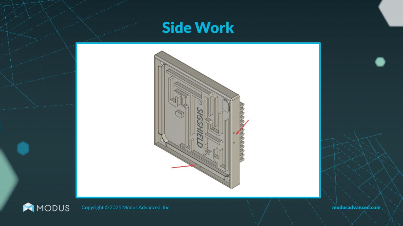
Avoid Side Work in Multiple Orientations
Designs aren’t always simple, but simplicity is key when you need a part in 24 hours. One big way to save on time and costs is by keeping your side work as simple as possible.
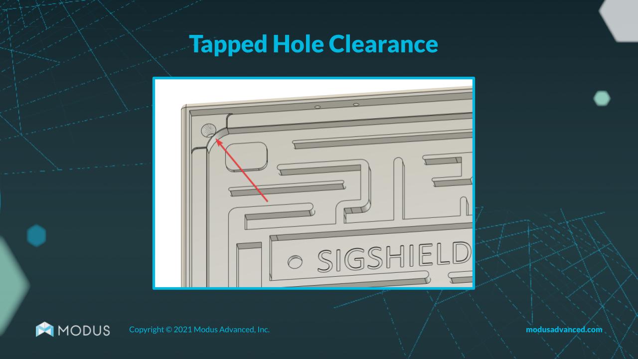
Give Tapped Holes Some Wall Clearance
Check the location of the tapped holes in your design. Are any close to the inside of a pocket? This creates a high likelihood that the tapped hole will break through the inside wall when the part is machine made. Breakout will cost time and money to fix.
Prefer Specified Edge Breaks Over Modeled Chamfers
Specifying your edge breaks can prevent machine operator errors during the CNC machining process that can cost a lot of money and time.
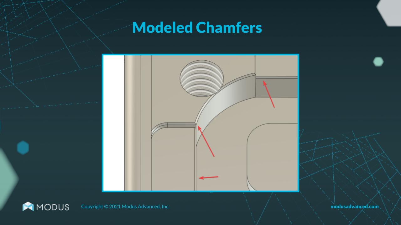
When you model the chamfer without specifying your edge breaks, it’s possible for the tech to select the wrong edge break when presented with multiple options.
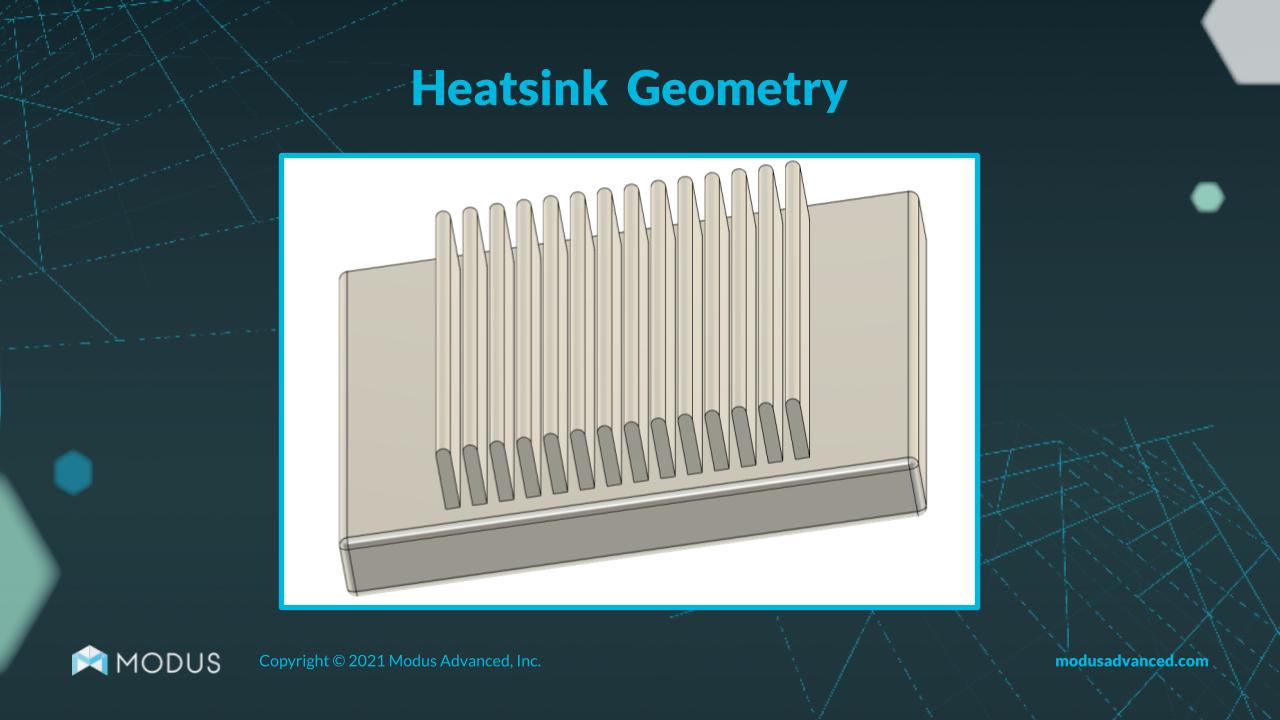
For Heatsinks, Go Wide
Heatsinks are usually no problem, but you can reduce lead times and costs for these parts if you keep a few design priorities in mind. If possible, avoid tall fins spaced very closely together. This kind of heatsink design adds a lot of cutting time and forces us to use a tool with a tiny diameter on multiple finishing passes to get the right surface finish on the CNC machine. Avoiding a rounded top corner on the fins can also save multiple finishing passes of the tool.
Design with Gasket Width in Mind
Avoiding gasket overflow is key to preventing problems with circuitry and avoiding longer lead and inspection times. If your housing's wall thickness or the width of the dispensed gasket don't match up, the fluid being dispensed can spill over the thin wall into the cavity, potentially causing shorting issues with whatever you are trying to shield.
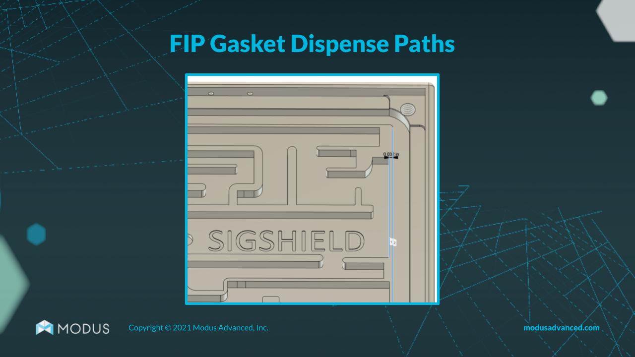
When possible, a wider wall is better than a thin wall, so try to design your housing with your gasket widths squarely in mind. The minimum recommended wall thickness for metal is 0.8mm and 1.5mm for plastics. Aim for consistent wall thickness to make it easier to dispense the gasket in the center and across the entire wall.
-- Article Continues Below --

Visit the Modus CNC Machining Resource Center
Compression Stops Over Grooves to Control FIP Gasket Height
We see a lot of form-in-place (FIP) designs come through with a gasket intended to be dispensed within a groove. This creates a number of potential issues.
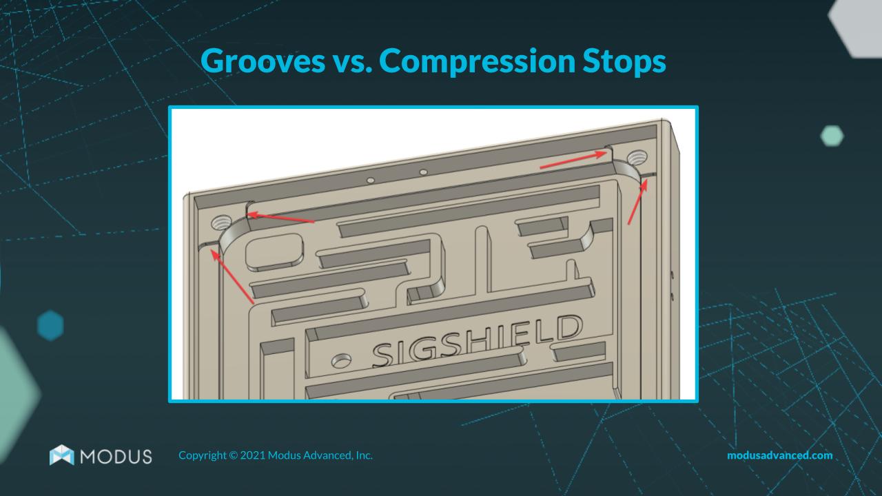
First, if fluid is being dispensed into the groove and the groove is relatively narrow, the fluid may contact the groove wall and cause the gasket to cure toward one wall rather than symmetrically in the center of the groove. This creates inconsistent compression forces and maybe even ineffective sealing.
How do you prevent this problem and save on inspection time and redesign costs? By designing with compression stops instead of grooves.
Instead of Small O-Ring Grooves, Use an FIP Gasket
If possible, try to use an FIP environmental gasket in your design instead of small O-ring grooves. Very small O-ring grooves take a lot of time to produce, which increases costs and total lead time.
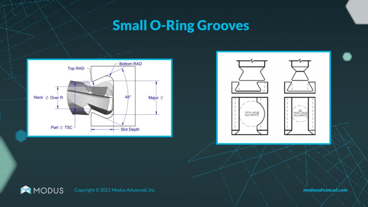
Instead of O-ring grooves, you could incorporate a flat surface with compression stops on which an environmental gasket could be dispensed. That could take your CNC machining time from over an hour to less than a minute.
Keep Hardware to a Minimum
Extra hardware in your design means extra costs and time during CNC machining. While helicoils and similar hardware are usually readily available, some more specialized hardware can take a long time to acquire. A few helicoils in a design is usually manageable, but a design with more than 50 might take much longer to machine. On CNC machine, it's much faster to tap a hole than to set up and validate a helicoil. To reduce your lead time and costs of CNC machining, keep extra hardware to a minimum.
For Quality Inspection Requirements, Be Specific
If certain dimensions in your design are going to be critical during the quality control inspection stage, specify those dimensions in your design. That gives us notice to focus on those. That is not to say, of course, that we will not be accurate with other dimensions, but we may not have to generate an inspection report for them, which can save on lead time for you.
When Setting Tolerances, Go Big When Possible
A lot of designs will incorporate boilerplate tolerance ranges on the title block. This is generally not a problem in the CNC machining phase, but if it's possible for your design to use a larger tolerance, that's preferable if you want to reduce lead time and manufacturing cost.
Larger tolerances make it easier for us to prove out the process, maintain stability and, ultimately, get the part back to you faster. Always choose the largest possible tolerance that still meets design requirementsModus Advanced Machined Parts: Less Lead Time, More Quality
With Modus Advanced machined parts, you don’t have to sacrifice quality for speed. You don’t have to bust your budget either. You can control your lead times and costs by implementing the above design features and speaking with our team of experts. To reach Modus Advanced, call 925-960-8700 or contact us online today.