
Silicone form-in-place (FIP) electromagnetic interference (EMI) shielding gaskets have a job to do. The electrically conductive FIP gasket bridges the gap between machined aluminum shields and PC boards create a faraday cage.
When designed correctly, machined aluminum shields with conductive material provide effective EMI shielding protection for sensitive electronics.
What does “designed correctly” mean?
There are obviously many factors that affect shielding performance. They’re all fun and exciting to talk about, but our focus in this blog post is on the use of mechanical compression stops to help avoid gasket-related issues.
Easy on the Torque
Some call it relaxation, but the commonly-used term to describe the apparent height decrease in a FIP gasket after being compressed is, you guessed it, “compression set”. When FIP gaskets are compressed within the typical 10 % to 50% range, they can form reliable EMI seals. When a conductive gasket is over-compressed, however, the conductive material may not rebound adequately when the compressive stresses are removed. Form-in-place gaskets can actually can be damaged when compressed more than 50%. Stops machined into the RF shield help avoid over-torque situations by limiting gasket compression.
Introducing the Mullins Effect
Engineers need to understand the basics of over-compression so they can find real-world solutions. Accordingly, they owe a debt of gratitude to the late Leonard Mullins, a rubber scientist known for his research on the stress-softening of elastomers, or silicone in the case of FIP gaskets.
The Mullins Effect describes how elastomers anisotropically stress-soften after repeated load-and-unload cycles – such as the tightening and loosening of screws. Anisotropy, the property of being directionally dependent, happens when a material has different properties in different directions. When a material behaves in this way, its mechanical properties may seem unpredictable.

SigShield: So Much More than RF Shielding.
Elastomers aren’t the only anisotropic materials, but they can be especially challenging because their material properties vary with loads. The direction of compression and the number of load-and-unload cycles affect those properties. Consequently, the torquing, loosening, and re-torquing of screws in EMI assemblies can be problematic.
Material scientists are still seeking to understand why elastomers stress-soften, but engineers are tasked with preventing this problem, or at least managing its effects. Relaxation and compression set of the gasket material can pose significant challenges. So, what’s the solution to overcoming the Mullins Effect? Compression stops!
Visit the Modus RF Shielding Resource Center
Compression Stops to the Rescue
In a gasket, stress is created when a force is applied, and the elastomer’s “push back” or reciprocating force diminishes. Typically, gasket relaxation occurs within an hour of assembly. Once a gasket is relaxed, the reciprocating force may only be 75% of the original force. In the case of a typical PCB board attached to an RF shield, the PCB could “float” if the gasket doesn’t rebound enough to make contact with the board. The situation would then need to be corrected by additional tightening of screws to ensure proper gasket to PCB contact.

Read Everything You Need To Know About RF Shielding
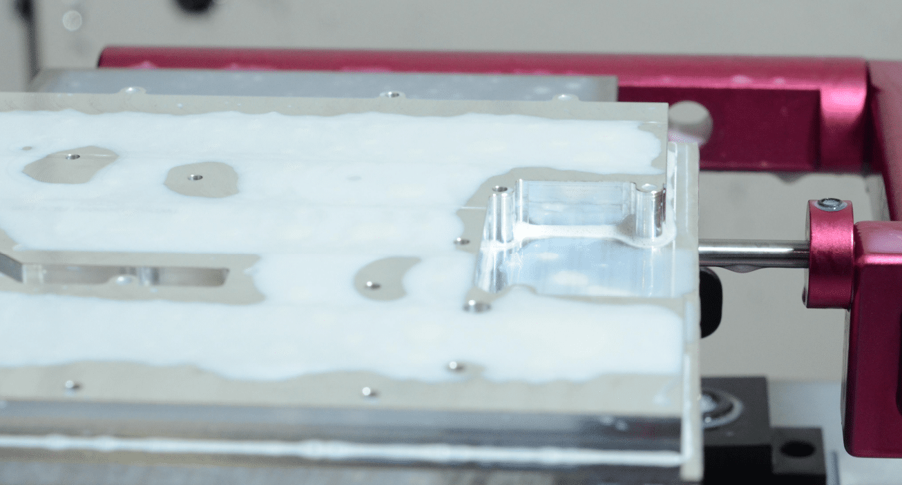
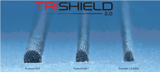
Our friends at Nolato Silikonteknik studied the effect of repeated compression and relaxation cycles on their Trishield® 2.0 number 8950 form-in-place gasket material. The 8950 was originally dispensed at a height of 1.6 mm with compression stops machined 1 mm above the gasket shelf. With an applied compression of 38%, the 1 mm tall compression stops provided the desired metal to metal contact.
After the first one hour compression cycle, the gasket height rebounded to 1.48 mm. The gasket was then allowed to relax for an hour and then subjected to a second one hour compression cycle. After the second cycle, the gasket height measured 1.47 mm. After 5 compression/release cycles, the final gasket height measured 1.47 mm. This, of course, is equal to a compression set of 22%.
Source: Nolato Silikonteknik
The use of compression stops and the recommended compression force produced acceptable results. The normal relaxation of the elastomer occurred, but the screws didn’t require additional tightening to fill the gaps because the built-in stops controlled the compression of the FIP gasket.
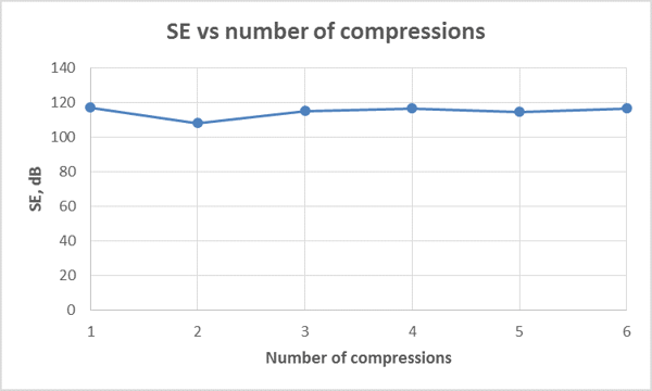
Furthermore, as seen in the graph below, the repeated compression cycles didn’t have a substantial effect on the RF shielding performance.
Key Takeaways
The biggest takeaway is compression stops machined into the RF shield will help avoid fastener-related gasket failures. Engineers should strive to design RF shield assemblies that take advantage of the natural strengths of dispensed FIP gaskets, while also remembering silicone gaskets need to relax a little in order to perform at their highest level.
To learn more about how Modus Advanced, Inc. solves EMI shielding challenges with form-in-place gaskets, please visit our website or request an onsite visit by one of our regional sales managers.
