Key Points
- Precision machining is defined by tolerance thresholds, not just equipment. Understanding where the line sits helps you specify correctly from the start
- Turning, milling, grinding, and Electrical Discharge Machining (EDM) each occupy a distinct role in the process hierarchy, with different cost, time, and geometry implications
- Sharp internal corners, deep pockets, and unnecessary five-axis features are the fastest ways to add cost and lead time to a machined part
- Standard Computer Numerical Control (CNC) tolerances run ±0.25 mm (±0.010"); going tighter requires justification because it extends lead time and raises cost
- The right process match at the design stage prevents expensive rework and keeps your program on schedule
What Precision Machining Means
The word "precision" gets applied loosely in manufacturing. Shops use it to mean anything from consistent quality to sub-micron control. For engineers specifying parts, that ambiguity costs time and money.
Precision machining is a material-removal discipline where dimensional accuracy is controlled tightly enough that the resulting part performs a specific mechanical, electrical, or structural function without tolerance stack-up creating failure risk. That threshold sits at approximately ±0.025 mm (±0.001") for general precision work, with tighter tolerances required for specific applications in aerospace, defense, and medical device manufacturing.
Standard CNC machining holds ±0.25 mm (±0.010") as the baseline for metal components. Moving from that baseline into precision territory typically means slower feeds, more controlled environments, additional inspection steps, and in some cases, entirely different processes. Every increment tighter carries a real cost and schedule implication.

Precision Machining Processes and What They're Good For
Precision machining isn't a single operation. It's a family of subtractive processes, each suited to different geometries, materials, and tolerance requirements. Knowing which process to specify, or which combination, is the design decision that drives everything downstream.
Turning
Turning rotates the workpiece against a stationary cutting tool. It's the right process for cylindrical features: shafts, bores, threads, tapers, and any geometry with rotational symmetry. CNC lathes with live tooling can add milled features in the same setup, reducing the number of operations needed.
Turning is efficient and well-suited to tight diameter tolerances. When you need a precision bore or a shaft with a controlled fit, turning is typically the first operation in the sequence.
Milling
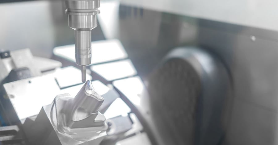
Milling moves a rotating cutting tool against a stationary or indexed workpiece. It handles prismatic parts, pockets, slots, contoured surfaces, and complex three-dimensional geometry. Three-axis milling covers the majority of precision work. Five-axis milling unlocks undercuts, compound angles, and features that would otherwise require multiple setups, but it carries a meaningful cost and schedule premium. For a detailed head-to-head breakdown of when five-axis is worth it, see the 5-axis vs. 3-axis CNC precision machining guide.
The fundamental physical constraint in milling is tool geometry. An end mill is cylindrical. It cannot cut a true 90-degree internal corner. Every internal corner in a milled pocket requires a radius, and that radius must be larger than the tool radius used to cut it. Designing internal corners smaller than the tool radius forces the shop to use a smaller tool, which deflects more, runs slower, and introduces dimensional risk. Modus Advanced's DFM framework recommends a minimum internal corner radius of 0.13 mm (0.005") with 1.52 mm (0.060") recommended for deep pockets where tool deflection becomes a meaningful factor.
Grinding
Grinding uses an abrasive wheel to remove small amounts of material with very high dimensional control. It's the process to specify when tolerances go tighter than standard milling can reliably hold, or when surface finish requirements are driven by sealing, bearing contact, or sliding fit applications.
Cylindrical grinding handles shafts and bores. Surface grinding works on flat features. Grinding is almost always a finishing operation; it follows rough and finish milling, and it's not where you start. Designing parts that require grinding adds operations, handling, and setup time. Specify it only when the function genuinely demands it.
EDM
Electrical Discharge Machining (EDM) removes material through controlled electrical sparks rather than cutting tools. It's the correct process for sharp internal corners, very narrow slots, and features in hardened materials that would break a conventional cutting tool.
EDM is also the answer when a designer has inadvertently created a geometry that milling can't reach. Features that require sharp internal corners or very small radii, below what end mill geometry allows, push a job into EDM territory. Wire EDM can hold tolerances comparable to finish grinding. Sinker EDM produces complex cavity geometries in hardened steel. Both are slower and more expensive than milling. If a feature can be redesigned with a slightly larger radius to avoid EDM, that change almost always reduces cost and lead time.
Essential Background Reading:
- What Is Considered a Tight Tolerance in Machining: Engineering standards that define the precision/standard threshold, with practical examples for design engineers.
- Machining Tolerance Chart, Standard vs. Tight Tolerances: A reference chart mapping tolerance bands to processes, cost tiers, and manufacturing implications.
- CNC Machine Tolerance Capabilities: What modern CNC equipment can and cannot deliver, and how to confirm your shop can hold your callouts.
- 5-Axis vs. 3-Axis CNC Precision Machining: A head-to-head comparison of machining configurations, cost, complexity, and geometry suitability, for engineers specifying setups.
Tolerance Thresholds That Define Precision Machining
Understanding where "standard" ends and "precision" begins matters when you're writing a drawing. The table below shows how tolerance bands map to processes and what each implies for cost and schedule.
Every Increment Tighter Carries a Cost
Where standard ends and precision begins, which process holds each band, and what the step costs in schedule and dollars. Deltas are relative to the standard CNC baseline.
The takeaway isn't that tighter is better. Tighter has consequences. Over-specified tolerances are one of the most common design mistakes that delay production and inflate cost without improving part performance, so tolerance the dimensions that are functionally critical and leave everything else at standard.
"Tolerances tighter than standard should appear on a drawing only when the function of the part … genuinely requires them."

The takeaway isn't that tighter is better. Tighter has consequences. Tolerances tighter than standard should appear on a drawing only when the function of the part, not aesthetic preference or conservative engineering habit, genuinely requires them. According to Modus Advanced's DFM framework, over-specified tolerances are one of the most common design mistakes that delay production and inflate cost without improving part performance.
Related Content:
- The Hidden Cost of Tight Tolerance: Why over-specifying tolerances inflates lead time and cost without improving part performance. With practical guidance for drawing review.
- Tolerance Stack-Up Nightmares: How cumulative tolerance errors propagate through an assembly and how to choose callouts that prevent it.
- Tolerance Design and Manufacturing Feasibility: Bridging the gap between what's specified on the drawing and what the manufacturing process can reliably produce.
- Engineering Tolerance Design Considerations: Design-stage decisions that make tolerances achievable and keep processes in statistical control.
- Tight Tolerance Manufacturing Processes and Quality Control: How precision manufacturing shops maintain process control and verify conformance at demanding tolerance bands.
Corner Radius Requirements in Precision Machined Parts
Corner radius is one of the most consequential design decisions in a machined part, and one of the least discussed. The table below captures the requirements directly from Modus Advanced's DFM guidelines.
| Feature Type | Minimum Radius | Recommended Radius | Manufacturing Benefit |
|---|---|---|---|
| Internal corners | 0.13 mm (0.005") | 0.76 mm (0.030") | Standard tooling compatibility |
| Deep pockets | 0.25 mm (0.010") | 1.52 mm (0.060") | Reduced tool deflection |
| Thin wall features | 0.51 mm (0.020") | 2.03 mm (0.080") | Improved rigidity during cutting |
Larger radii enable the use of larger, more rigid cutting tools. Rigid tools resist deflection, run faster, and deliver better surface finish. Specifying radii that match standard tooling sizes eliminates the need for custom or small-diameter tooling with extended lead times. When a corner radius falls below the minimum threshold for milling, the feature routes to EDM, which adds time, cost, and process complexity. Getting the radius right at the design stage keeps the part in the correct process from the start.
Design Decisions That Drive Process Complexity
A few specific design choices determine most of the cost and schedule variance in a precision machined part. They appear regularly on drawings from engineers who haven't yet had the machining shop conversation.
- Internal corner radius: Specify corners as large as the function allows. Small radii force smaller tools, which deflect more and run slower, increasing both cost and dimensional risk.
- Pocket depth-to-width ratio: Deep, narrow pockets limit tool rigidity. Keeping pocket depth proportional to tool diameter reduces deflection risk and keeps tolerances achievable.
- Five-axis features: Compound angles and undercuts that require five-axis machining carry a setup premium. If a feature can be oriented to three-axis access without functional compromise, redesign it.
- Feature alignment: Aligning features to three orthogonal axes reduces setup count. Every additional setup introduces a datum shift and a tolerance accumulation risk.
- Critical dimension callouts: Tolerance every dimension that matters. Leave reference dimensions as reference. Tolerancing everything equally forces inspection effort onto features that don't affect function and buries the ones that do.
- Surface finish specification: Specify finish by function. A mating surface that sees a dynamic seal needs a specific Ra value. A pocket floor that doesn't contact anything doesn't. Over-calling surface finish requirements adds operations.
For a deeper treatment of how these decisions affect cost and part quality, see precision machined parts: design considerations that determine cost and quality.
Next Steps:
- Precision Machined Parts. Design Considerations: DFM principles specific to machined parts: tolerancing, feature accessibility, material selection, and surface finish callouts that reduce cost and rework.
- High Precision Machining. When Standard Tolerances Aren't Enough: Sub-micron tolerances, environmental controls, RF physics of machined enclosures, and inspection methods for demanding applications.
- Precision Machined Components. Inspection and Metrology: CMM measurement, GD&T verification, certificates of conformance, and the machining-to-inspection loop that protects your assembly.
- Precision Machining Parts. How Material Choice Drives Tolerances: How substrate selection drives achievable tolerances, surface finish, distortion risk, tool wear, and lead time.
- Precision Parts Manufacturing. Scaling from Prototype to Production: Process validation, fixturing consistency, and inspection scaling for programs moving from first article to full production.
When Precision Machining Is the Right Answer
Not every application needs it, and that's the point. Standard CNC tolerances cover a significant portion of structural, housing, and bracket applications in aerospace, defense, and medical device programs. Precision machining belongs where the part's function demands it.
RF shield enclosures are a good example. The housing needs to close reliably, the mating faces need to seal consistently, and the wall features need to hold position relative to the RF ground plane. That's a precision application. A structural bracket holding a cable harness in position is not. Over-tolerancing it slows production and adds cost to a part that doesn't need it.
The question to answer at the design stage is what the part actually does and where dimensional variation would cause functional failure. That conversation, between the design engineer and the manufacturing engineer, is where the right tolerance callout gets established. Modus Advanced's engineering team engages directly with design engineers in DFM reviews to work through exactly that question before the drawing is finalized.
See It In Action:
- Aerospace Parts Manufacturing. Precision Components for Critical Applications: How precision machining requirements play out in aerospace programs where dimensional variation directly affects mission success.
- Complex Tight-Tolerance CNC Machining for Medical Devices: Real-world examples of precision CNC machining applied to life-critical medical device components.
- Why Aerospace and Defense Companies Partner with Modus Advanced: How precision manufacturing capability and mission-critical timeline management come together for defense programs.
- Component Manufacturing for Satellite Communication Systems: Precision engineering for space applications where parts must perform without the possibility of field repair or replacement.
Applying Process Selection Logic at the Design Stage
Getting the process match right early prevents the two most expensive outcomes in precision machined parts: a drawing that can't be held to tolerance in the specified process, and a drawing that could be held easily but costs twice what it should because tolerances were over-called.
The practical steps at the design stage are straightforward. Identify which dimensions are functionally critical and tolerance those specifically. Leave everything else at standard. Choose internal corner radii that match the tool sizes your shop is likely to run. Avoid five-axis features where three-axis geometry works. When a feature looks like it requires EDM, ask whether a small redesign eliminates that requirement.
Understanding how to evaluate a precision machine shop before you send a drawing helps you confirm whether your supplier can actually hold the tolerances you need. The right contract manufacturing partner catches these issues in DFM review, not after the first article inspection.
Precision machining exists because some applications genuinely need it. A surgical instrument. An aerospace enclosure carrying RF-sensitive electronics. A defense system component that has to perform under conditions where replacement isn't an option. In those cases, holding the tolerance isn't a preference. It's the mission. Specifying correctly from the start means the part ships on time, within budget, and built for what it actually has to do.
Frequently Asked Questions About Precision Machining
What tolerance is considered precision machining?
Precision machining generally begins at tolerances tighter than ±0.13 mm (±0.005"), with general precision work typically holding ±0.025 mm (±0.001") or better. Standard CNC machining operates at ±0.25 mm (±0.010") as a baseline. Tolerances in the ±0.05-0.13 mm (±0.002"-0.005") range are considered precision-tier and require finish milling or precision turning with tighter process controls. Tolerances below ±0.013 mm (±0.0005") require grinding, lapping, or EDM, along with environmental controls such as temperature stabilization and machine warm-up procedures.
What is the difference between standard machining and precision machining?
Standard CNC machining holds tolerances in the range of ±0.25 mm (±0.010") and is appropriate for structural components, housings, and brackets where dimensional variation doesn't create functional failure risk. Precision machining holds tolerances from ±0.025-0.13 mm (±0.001"-0.005") or tighter, requires more controlled processes, and is used where parts must perform critical mechanical, electrical, or structural functions without tolerance stack-up causing failure. The distinction is functional, not cosmetic: precision machining is justified when the application demands it, not as a default specification.
When should I use EDM instead of CNC milling?
Electrical Discharge Machining (EDM) is the correct process choice in three situations: when a part requires sharp internal corners that a cylindrical end mill cannot produce, when features must be cut in hardened materials that would break conventional cutting tools, and when feature geometry is too fine or complex for milling to reach reliably. Wire EDM holds tolerances comparable to finish grinding and is used for narrow slots and external profiles. Sinker EDM produces complex cavity geometries in hardened steel. Both processes are slower and more expensive than milling, so if a design can be modified to increase internal corner radii and avoid EDM, that redesign almost always reduces cost and lead time.
How do tolerances affect lead time and cost in precision machining?
Tighter tolerances require slower cutting feeds, more controlled machine environments, additional inspection steps, and in some cases entirely different processes, all of which extend lead time and increase cost. Moving from standard CNC tolerances (±0.25 mm / ±0.010") to precision-tier (±0.05-0.13 mm / ±0.002"-0.005") typically adds 25-50% to lead time and 50-100% to cost. Tolerances in the high-precision range (±0.013-0.025 mm / ±0.0005"-0.001") add 100-200% to lead time and 200-400% to cost, and require environmental controls such as temperature-stabilized machining environments and stress-relief operations between cuts. Ultra-precision work below ±0.005 mm (±0.0002") can add 300% or more to lead time and 500% or more to cost.
What are the corner radius requirements for CNC machined parts?
Internal corners in CNC milled parts require a radius because cylindrical end mills cannot cut true 90-degree internal corners. The minimum internal corner radius for standard tooling compatibility is 0.13 mm (0.005"), with 0.76 mm (0.030") recommended. Deep pocket corners require a minimum of 0.25 mm (0.010"), with 1.52 mm (0.060") recommended to reduce tool deflection. Thin wall features require a minimum of 0.51 mm (0.020"), with 2.03 mm (0.080") recommended to maintain rigidity during cutting. When corner radii fall below the minimum thresholds for milling, the feature must be produced by EDM, which adds cost and extends lead time.
What processes are used in precision machining?
Precision machining uses four primary processes, each suited to different geometries and tolerance requirements. Turning rotates the workpiece against a stationary cutting tool and is used for cylindrical features such as shafts, bores, and threads. Milling moves a rotating tool against the workpiece and handles prismatic parts, pockets, slots, and complex surfaces in three-axis or five-axis configurations. Grinding uses an abrasive wheel for high-accuracy finishing when tolerances exceed what milling can reliably hold. EDM removes material through controlled electrical sparks and is used for sharp internal corners, hardened materials, and geometries that conventional cutting tools cannot reach. Most precision machined parts require a combination of these processes in sequence. For a comprehensive view of how these processes fit into the broader precision manufacturing landscape, see the full precision manufacturing overview.