Designing a form-in-place (FIP) electromagnetic interference (EMI) gasket can be challenging. If you're not prepared, it can feel next to impossible. However, with the tips discussed in this blog post, designing a conductive shielding FIP gasket can be relatively straightforward.
Partnering with the expert team at Modus Advanced makes it even easier. From idea to ignition, we’re your dedicated partner as you design and manufacture a form-in-place EMI gasket. Read on to learn more about how to optimize your design for effective EMI shielding.
If you need information about FIP gaskets, you can find everything you’d ever want to know in our comprehensive FIP gasket guide. Check it out.

Visit the Modus Form-in-Place Gasket Resource Center
1. Maintain Distance Between Ferrous Materials and FIP EMI Gaskets
This guidance is specific to materials that must be cured through a magnetic forming process.
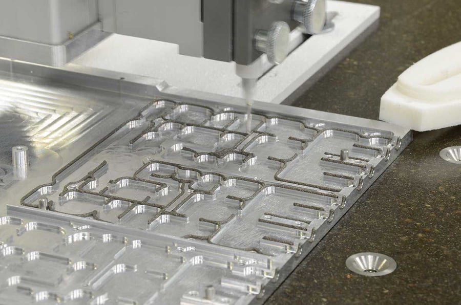
When you dispense an FIP conductive shielding gasket, it is in the form of a thick liquid. That liquid contains both your base gasket material and your conductive filler material — the part that makes the gasket conductive and shields against EMI. The liquid has to cure to form a solid form-in-place EMI gasket, and the curing process is extremely sensitive.
Curing can present a hazard to your gasket design if the part on which you are dispensing the gasket contains ferromagnetic material. That’s because the magnetic properties of the material can attract the filler metals in the newly dispensed and uncured gasket. This can cause the gasket to cure improperly.
For example, if you have a pin that contains a ferrous material too close to the vertical configuration where you intend for your gasket to form, the gasket may cure in the direction of the magnetic pin — not toward the walls of the gasket path. You can prevent this problem by ensuring no potentially magnetic materials are too close to where your form-in-place EMI gasket will be.
In addition, using non-ferrous components or ensuring adequate spacing from ferromagnetic materials can significantly enhance the performance of your form in place gaskets by preventing unintended magnetic interference during curing.
2. Choose Conductive Shielding Gasket Filler Materials Wisely
With standard environmental FIP gaskets, you only have to choose one kind of material: the base. But form-in-place EMI gaskets require selecting an additional material: your filler material. This is one of the most important decisions you will make in the design process.
The standard EMI gaskets filler materials include:
- Silver
- Silver copper
- Silver nickel
- Silver aluminum
- Nickel graphite
- Nickel aluminum
Each filler material offers unique price points and characteristics but they all serve to make the gasket conductive and resistant to EMI.
To choose wisely, begin by considering your budget. Silver tends to be the most expensive filler material but is high-quality and sometimes ideal for form-in-place EMI gasket projects with large budgets. Because the FIP gaskets manufacturing process produces so little material waste, your budget may accommodate more expensive filler materials.
Nickel graphite tends to be more affordable but consider compatibility with materials it will contact on the part. Corrosion can occur when certain metals come into contact with other metals or environments, so your filler material choice must account for these factors.
Moreover, exploring options like silver plated aluminum or silver plated copper might offer additional benefits in terms of cost-effectiveness while maintaining necessary conductivity levels required for effective shielding solutions.
3. Compression Force Matters for FIP EMI Gaskets
More so than for other types of gaskets, conductive shielding gasket designs must consider compression force requirements for their materials.
An FIP EMI gasket must be compressed under exact pressure as specified by material manufacturers, or else you risk a failure to create a seal. The precise application of compression force ensures that each dispensed gasket maintains its integrity and provides reliable sealing throughout its operational lifespan.

Read everything you ever wanted to know about FIP gaskets.
4. Stay Out of Grooves for Form-in-Place EMI Gaskets
For the most part, avoid having grooves in your FIP dispense path.
Why?
Because dispensing liquid gasket material into a narrow groove can cause it to cure toward groove walls rather than its center. That can lead to improper sealing and spotty compression forces.
The good news is there’s a quick fix: design compression stops where grooves would have been placed. By designing flat surfaces or using strategically placed compression stops instead of grooves, you ensure that your form-in-place gaskets cure uniformly without compromising their sealing capabilities.
Additionally, avoiding grooves helps maintain consistent thickness across all sections of your gaskets, thereby enhancing their overall effectiveness against electromagnetic interference while providing an excellent environmental seal.
5. Avoid Sloping Surfaces
FIP EMI gaskets are intricate, making them ideal for complex designs; however, avoid slopes when designing dispensing paths if possible. The reason is simple: FIP conductive gaskets are applied as liquids, which move downward. Steeper slopes make dispensing challenging, ultimately increasing costs and lead times on parts.
Ensuring flat or minimally sloped surfaces helps maintain consistent application thickness across all sections of your form in place gasket, thereby enhancing its overall effectiveness against electromagnetic interference while providing an excellent environmental seal. 
Get the guide to EMI Gasket Design
6. Opt for Vertical Integration
This tip is less about form-in-place EMI gasket design and more about what comes before and after it. It stands to reason that if you’re designing a gasket, that gasket will be dispensed on another part of the device.
Who will manufacture those other parts? How expensive and time-consuming will it be to have parts manufactured at one place and then sent elsewhere for gasket application? Will all manufacturers maintain consistent quality?
Splitting up manufacturing introduces risks; hence focusing on vertical integration wherever possible is crucial. In other words, try having one manufacturer for all device parts, including gaskets.
At Modus Advanced, vertical integration is key focus area – enabling us through SigShield™ technology – to significantly reduce typical lead times by machining metal housing, applying coatings/platings, and dispensing your FIP EMI gasket efficiently.
FIP EMI Gaskets: From Concept to Creation with Modus Advanced
There’s a lot to consider when you’re designing a form-in-place EMI gasket. Miss a step or fail to implement one of the tips above, and you’re in for a frustrating, expensive experience. We’re here to make sure that doesn’t happen to you. Our engineering and manufacturing professionals are prepared to be your partner as you move forward with your conductive shielding gasket.
If you’re ready to team up with the last gasket manufacturing partner you will ever need, all you have to do is get in touch with us. Reach out to the team at Modus Advanced by calling (925) 960-8700 or contacting us online.
