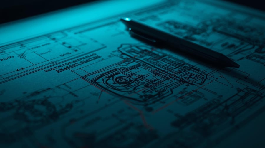
CNC Machining Drawing Errors: The Drawing Is the Contract
A CNC machining drawing is a complete, unambiguous manufacturing specification. Every dimension, tolerance, feature, and note on that drawing is an instruction. When those instructions are clear, consistent, and physically achievable, the machine shop can produce your part accurately and quickly. When they're not, everything slows down.
The relationship between drawing quality and lead time is direct and consistent. A drawing that requires three revision cycles before production starts has added multiple weeks to the program. A drawing with impossible features — features that no CNC machine can produce as dimensioned — may never result in a correct part until the design is changed.
This isn't a criticism of the engineers who produce these drawings. Many of the most common CNC machining drawing errors come from designers who are excellent at their domain — mechanical analysis, circuit design, system architecture — but who haven't yet spent time on a shop floor watching how machining actually works. The geometry that makes complete sense in CAD can be physically impossible on a three-axis mill.
What follows is a rundown of the most common drawing errors, why each one is a problem, and how to avoid them before the drawing hits the quote desk.

Error 1: Square Internal Corners
Square internal corners are the single most common machining drawing error, and they show up everywhere from student projects to production programs. The problem is intuitive once you understand how a mill works — but completely invisible until you do.
CNC milling uses a rotating cylindrical tool. The tool has a radius. When that tool travels into an internal corner — a pocket, a slot, a counterbore with a perpendicular wall — it leaves a radius behind. The radius of the corner equals (at minimum) the radius of the tool. A square internal corner, by definition, has a radius of zero. A rotating tool cannot produce a zero-radius corner.
Every square internal corner on a machining drawing requires a conversation with the manufacturing team. The resolution is usually one of three things: the designer adds a corner radius callout that the machine can produce, the shop requests an engineering change to add the radius, or (in rare cases) an EDM (electrical discharge machining) operation is added to produce the square corner — at significant cost and lead time penalty.
How to Avoid Square Internal Corners
Internal corner radii should be added to all internal pocket and slot features during the design phase. Several straightforward practices prevent this error from reaching the shop floor:
- Add a minimum radius note to your drawing: For features without a specific corner radius requirement, a general note ("UNLESS OTHERWISE NOTED, INTERNAL RADII 0.51 mm (0.020") MIN") gives the machinist latitude to use standard tooling.
- Size the radius to the tool depth: The minimum corner radius should equal or exceed the tool radius needed to reach the feature depth — a shallow pocket can use a smaller radius than a deep one.
- Flag true square corner requirements explicitly: If a mating component genuinely requires a square internal corner, call it out and discuss it with the machining team before the drawing is finalized — not after the first article comes back with a radius.
Essential Background Reading:
- CNC Machining at Modus Advanced: Overview of 3-axis, 5-axis, horizontal, and vertical machining capabilities, standard tolerances, and program support from prototype through production.
- Design for Manufacturability — CNC Machined Metal Parts: Complete Engineering Guide: The comprehensive DFM reference for machined components — feature design, tolerance specification, material selection, and process optimization.
- CNC Machine Tolerance Capabilities — Understanding What Your Shop Can Deliver: What standard, precision, and high-precision tolerances actually mean in practice — and what they cost.
Error 2: Tapped Holes Without Thread Runout Clearance
Tapped holes are ubiquitous in machined assemblies. They're also a reliable source of machining errors when the drawing doesn't account for the geometry of the tapping tool.
A tap — the tool used to cut threads into a hole — has a cutting portion at the tip and a body behind it. When the tap reaches the bottom of a blind hole, the cutting portion needs room to pass through the last few threads before the body of the tap contacts the hole floor. That clearance distance — from the last full thread to the bottom of the hole — is the thread runout zone.
If the hole isn't deep enough to provide that clearance, the tap contacts the bottom of the hole before it finishes cutting threads. The result is either a broken tap (bad), an undertapped hole that the fastener won't seat in (also bad), or a non-conforming part that requires rework (consistently bad).
The standard specification for thread runout clearance is available in machinist's handbooks and tap vendor documentation. It varies by thread size and tap geometry, but as a rule of thumb, a minimum of 1.5 to 2 thread pitches of clearance beyond the last full thread is a safe starting point.
How to Avoid Tapped Hole Depth Errors
When dimensioning tapped holes, specify both the total hole depth and the minimum full-thread depth. Don't dimension only the full-thread depth and assume the machinist will provide adequate runout clearance — specify the total hole depth explicitly. Review tap manufacturer specifications for the specific thread size you're using and confirm that your hole depth provides adequate runout clearance before the drawing is released.
Error 3: Over-Constrained Dimensions
Over-constrained drawings — drawings where more dimensions are specified than are necessary to fully define the geometry — create a specific and frustrating type of manufacturing problem. When every dimension is specified, including redundant or derived dimensions, even small manufacturing variation can create a technically non-conforming part that is functionally perfect.
The most common version of this problem: a drawing specifies the location of a feature from two different datums, plus the distance between those datums. Three dimensions for what is fully defined by two. When the machined part has the feature in the correct location relative to both datums but the math doesn't close perfectly due to accumulated tolerance, the part fails inspection — even though it will assemble and function correctly.
Over-constrained drawings also make the machine shop's job harder. When every dimension must be held to tolerance, the machinist has less freedom to optimize their toolpath and fixturing for efficiency. Parts take longer and cost more to produce.
How to Avoid Over-Constrained CNC Machining Drawings
Dimension the minimum set of measurements required to fully define the part geometry — no more. Use GD&T (Geometric Dimensioning and Tolerancing) reference dimensions for information-only callouts that shouldn't be inspection requirements. Have someone who wasn't involved in creating the drawing review the dimension scheme before release.
If you're not sure whether a dimension is necessary or redundant, ask. A manufacturing partner with engineering support can review dimension schemes during DFM review and flag over-constrained features before they create inspection problems.
Error 4: Tolerances Tighter Than the Application Requires
Standard CNC machining tolerance at Modus Advanced is ±0.25 mm (±0.010"). That tolerance covers the vast majority of machined component requirements in aerospace, defense, and medical device applications. It's achievable at standard production speed and cost, and it represents genuine capability — not a conservative estimate padded for safety.
Tighter tolerances are achievable. ±0.13 mm (±0.005") and tighter are possible with advanced fixturing, precision tooling, and slower cycle times. But they cost more, take longer, and require more rigorous inspection. If the functional requirement of the part doesn't actually demand a tighter tolerance, specifying one is a direct cost penalty with no performance benefit.
The most common scenario: a design team applies a single title block tolerance to all features on a drawing without evaluating whether each feature actually needs that precision. The result is a part that requires tight tolerance machining on features — housing ODs, non-mating surfaces, clearance holes — that would function perfectly well at standard tolerance.
How to Right-Size CNC Machining Tolerances
Evaluate each toleranced feature against its actual functional requirement before the drawing is released. The decision is usually straightforward once the question is asked directly:
- Mating surfaces, precision bores, and locating features: These interface with other precision components and may genuinely require tolerances tighter than standard. Evaluate against the mating part's tolerance to determine what's actually needed.
- Non-mating surfaces, ODs, and clearance holes: These rarely have a functional precision requirement. Standard tolerance of ±0.25 mm (±0.010") is almost always sufficient — specifying tighter adds cost with no benefit.
- Reference features and cosmetic surfaces: These should carry reference dimensions, not toleranced dimensions. They are not inspection requirements.
Use zone tolerancing where possible — tight callouts only on the features that need them, standard tolerance on everything else. The machinist can then optimize the production sequence around what actually matters, reducing cycle time and cost without touching part performance.
The following table illustrates the cost and lead time implications of tolerance specification:
Tolerance Level | Standard Capability | Typical Application | Lead Time Impact | Cost Impact |
±0.25 mm (±0.010") | Standard | General machined features, non-mating surfaces | Baseline | Baseline |
±0.13 mm (±0.005") | Precision | Close-clearance fits, precision bores, mating surfaces | Moderate increase | Moderate increase |
±0.05 mm (±0.002") and tighter | High precision | Precision instrument components, critical mating features | Significant increase | Significant increase |
Error 5: Missing or Incomplete CAD Files
This one isn't a geometry error — it's a process error, but it causes the same result: delay.
CNC machining requires a CAD model to generate toolpaths. A drawing without an associated 3D CAD file means the machining team has to reconstruct the 3D model from the 2D drawing before programming can begin. That reconstruction takes time, introduces risk of interpretation error, and delays the quote.
Even more disruptive: a 2D drawing that carries insufficient information to fully reconstruct the 3D model. Ambiguous views, missing cross-sections, or conflicting dimensions can result in a reconstructed model that doesn't match design intent — and a first article that requires revision before it's even inspected.
How to Submit CNC Drawings Properly
Always submit a native 3D CAD file with every RFQ. STEP format (.stp / .step) is widely compatible and preserves the geometry accurately. Include the 2D drawing as the controlling document for tolerance, material, and finish callouts — but let the 3D model define the geometry.
If a drawing has been created from a CAD model, confirm that the 2D drawing accurately reflects the current model revision before releasing both documents together.
Related Content:
- Sharp Corners on CNC Machined Parts — The Impossible Feature That's Killing Your Timeline: A focused deep-dive on the square internal corner problem — why it happens, what the options are, and how to specify your way out of it.
- The Hidden Cost of Tight Tolerance — Why Tighter Isn't Always Better: The real cost and lead time impact of over-specifying tolerances on machined parts — with guidance on right-sizing specs for each feature type.
- Tolerance Design and Manufacturing Feasibility: How to right-size tolerances across CNC machining, FIP dispensing, and converting — the complete tolerance decision framework.
- When Casting Meets Machining in Production Strategy: How to redesign cast geometry for CNC machining — removing draft angles and simplifying features that add hours of cycle time when machined.
Error 6: Features Designed for Casting, Submitted for Machining
This error is less common but worth understanding because it creates some of the most complex DFM conversations. It happens when a part is designed for casting — with all the geometric compromises that casting requires — and then submitted for CNC machining as a prototype or low-volume alternative.
Cast parts are designed with draft angles on vertical walls. Draft — typically 1–3 degrees of taper — allows the part to be released from the mold without tearing the casting. On a machined part, draft angles on walls require 5-axis machining (or complex 3+2 setups) and ball-end mill operations that are slow and expensive. Features that are simple in a casting become hours of machining time.
Additionally, some geometric features that are achievable in casting — complex undercuts, internal cavities, intricate organic forms — are physically impossible on a CNC machine without multi-step operations or alternative processes.
How to Redesign Cast Parts for CNC Machining
If a part will ultimately be cast in production but needs to be machined for early prototyping or testing, consider whether the design can be simplified for the machined version. Removing draft angles and simplifying complex cast features for the machined prototype will dramatically reduce cost and lead time.
If the cast geometry must be preserved exactly — for assembly compatibility or test validity — involve the machining team early to identify which features will require special operations, and factor the additional time and cost into the program plan.
The DFM Review: Catching CNC Machining Drawing Problems Before They Cost You
Every error on this list is catchable in a Design for Manufacturability (DFM) review before the drawing is released for production. That's the purpose of the DFM process — to apply manufacturing engineering judgment to a design while changes are still cheap.
A DFM review for a CNC machined part covers five areas:
- Feature manufacturability: Are all features physically achievable with standard CNC tooling — no square internal corners, no tapped holes without runout clearance, no inaccessible geometry?
- Tolerance review: Are specified tolerances achievable at standard conditions? Are any tighter than the application actually requires?
- Dimension scheme: Is the drawing fully but not over-constrained? Are GD\&T callouts applied correctly, with reference dimensions used for non-inspection features?
- Material and surface finish: Are specifications appropriate for the application and achievable with available processes?
- CAD completeness: Is the 3D model complete, accurate, and consistent with the 2D drawing revision?
The investment in a DFM review is small relative to the cost of a rework cycle. A drawing revision before production starts takes hours. A rework cycle after a failed first article takes weeks — and in a program where schedule matters, those weeks have consequences.
Frequently Asked Questions: CNC Machining Drawing Errors
Why do CNC machined parts fail inspection because of drawing errors?
CNC machined parts fail inspection from drawing errors primarily due to over-constrained dimensions, where redundant datum references create tolerance stack-up that makes a functionally perfect part technically non-conforming. Other common causes include features specified with tolerances tighter than the process can achieve at standard conditions and geometric callouts (like square internal corners) that are physically impossible to machine. A good manufacturing partner should be able to help give you design feedback to avoid these problems.
What is thread runout clearance and why does it matter?
Thread runout clearance is the distance from the last full thread to the bottom of a blind tapped hole — the space the tap needs to complete cutting threads before its body contacts the hole floor. Insufficient runout clearance causes broken taps, undertapped holes, or non-conforming parts. A minimum of 1.5 to 2 thread pitches of clearance beyond the last full thread is a reliable starting point.
How do I fix square internal corners on a CNC machining drawing?
Add a corner radius callout to all internal pocket and slot features. For features without a specific radius requirement, a general drawing note — "UNLESS OTHERWISE NOTED, INTERNAL RADII 0.51 mm (0.020") MIN" — gives the machinist latitude to use standard tooling. If a mating component genuinely requires a square corner, flag it explicitly and discuss EDM as an option with your manufacturing team before finalizing the drawing.
What file format should I submit with a CNC machining RFQ?
Submit a STEP format (.stp / .step) 3D CAD file with every RFQ. STEP is widely compatible and accurately preserves part geometry for toolpath generation. Include the 2D drawing as the controlling document for tolerances, material, and finish callouts. Submitting only a 2D drawing requires the machine shop to reconstruct the 3D model, adding time and creating interpretation risk.
When should I specify tolerances tighter than ±0.25 mm (±0.010") on a CNC machining drawing?
Specify tolerances tighter than ±0.25 mm (±0.010") only when the functional requirement of a specific feature genuinely demands it — mating surfaces, precision bores, and locating features that interface with other precision components are common examples. Non-mating surfaces, housing ODs, and clearance holes almost never need tighter callouts. Applying tight tolerances as a blanket drawing default adds cost and lead time with no performance benefit.
What is a DFM review for CNC machining?
A Design for Manufacturability (DFM) review is an engineering evaluation of a part drawing before it's released for production. For CNC machining, DFM review checks for: physically impossible features (square internal corners, insufficient runout clearance), over-constrained dimension schemes, tolerances tighter than the application requires, material and surface finish appropriateness, and CAD file completeness. DFM review catches drawing errors while revisions are inexpensive — not after a failed first article.
Next Steps:
- Submit Your Design for DFM Review: Get engineering feedback on your CNC machining drawing before it reaches the shop floor — catching errors while revisions are still inexpensive.
- Design for Manufacturability Resource Center: All of Modus Advanced's DFM resources in one place — guides, articles, and checklists for building parts that manufacture cleanly the first time.
- Design for Manufacturability Principles Every Engineer Should Know: The foundational DFM principles that prevent drawing errors across every manufacturing process — not just CNC machining.
- Depth vs. Breadth of Manufacturing Expertise: Which Is Best? Why a manufacturing partner with engineers across every department catches drawing errors that a single-process shop never will.
Modus Advanced: Engineers Who Review Your CNC Machining Drawing Before We Machine It
The DFM conversation is most valuable when the manufacturing partner has engineers who understand both the design intent and the production process — engineers who can propose a solution, not just identify a problem.
Modus Advanced employs engineers across every department, with engineers comprising more than 10% of our total staff. Our DFM review process is built into every quote, and our engineering team engages directly with customers to resolve design questions before they become manufacturing problems.
We operate 3-axis, 5-axis, horizontal, and vertical machining centers, and we support programs from rapid prototype through production. Our standard CNC machining tolerance is ±0.25 mm (±0.010"), with tighter tolerances achievable when the application genuinely requires it. We hold AS9100, ISO 9001, and ITAR certifications and support defense, aerospace, and medical device programs with the quality infrastructure those industries demand.
Bad drawings are the enemy of fast programs. Partner with a manufacturing team that helps you make better drawings — because one day matters, and the right design review can get your program back a week before it ever starts.
