Key Points
- Precision CNC (computer numerical control) machining delivers standard tolerances of ±0.25 mm (±0.010") in most shop environments, with tighter tolerances available at measurable cost and lead time premiums
- Multi-axis capability, particularly 5-axis, unlocks complex geometries in single setups, but not every part needs it, and specifying it unnecessarily adds cost
- Tool geometry is the fundamental constraint: cylindrical cutters cannot produce sharp internal corners, and every design that ignores this will be modified during production
- Surface finish, material selection, and volume suitability all interact in ways that affect both what's achievable and what it costs
- The most capable CNC shops are vertically integrated, moving your part from machined housing through finishing, gasket dispensing, and assembly without changing hands
Precision CNC (computer numerical control) machining is the default process for tight-tolerance metal parts across aerospace, defense, and medical device applications. Engineers know the name. Fewer understand what separates a well-executed CNC program from one that produces scrap, or what a shop's equipment configuration means for their part. This article covers the technology in enough depth to inform real decisions: what multi-axis machines can and can't do, how surface finish is specified and achieved, which materials machine cleanly, and what volume range CNC genuinely serves well. For a broader look at where CNC fits within precision manufacturing processes, tolerances, and industries, that pillar resource covers the full landscape.

What Machine Configuration Tells You About Capability
The machine type defines the geometry it can reach. Selecting the wrong configuration for a part's feature set leads to either impossible operations or unnecessary cost.
What Each Machine Can Reach
The same part, viewed from above, on three configurations. The difference isn't precision. It's how many faces come off in a single setup.
Swipe to compare all three.
If your features align with X, Y, and Z, you probably don't need 5-axis. Specifying it anyway costs money without adding value.
"The machine type defines the geometry it can reach."

Vertical machining centers (VMCs) are the workhorses. The spindle is oriented vertically, giving excellent visibility and straightforward fixturing. VMCs suit flatter workpieces requiring operations primarily on one face: plates, brackets, housings with features on a single side. Their limitation is access. A part with features on four or five faces requires multiple setups, each introducing fixturing variation.
Horizontal machining centers (HMCs) orient the spindle horizontally and use a pallet-based tombstone system that allows four-sided access in a single setup. They excel on large, heavy prismatic parts where gravity-assisted chip evacuation improves surface quality. For complex housings with features on multiple vertical faces, an HMC is often the more efficient path.
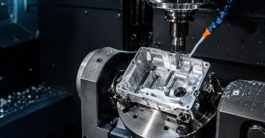
5-axis CNC machines move the cutting tool or part along five simultaneous axes, reaching compound angles and complex contours in a single setup. The capability is important for turbine blades, aerospace structural components, and medical implants with complex contoured surfaces. The Modus Advanced CNC machining capabilities page describes these as ideal for parts requiring tool access from multiple angles in a single setup.
The tradeoff is cost and programming complexity. If your features are alignable with X, Y, and Z axes, you probably don't need 5-axis, and specifying it anyway costs money without adding value. A head-to-head comparison of 5-axis vs. 3-axis CNC precision machining covers that decision in detail.
Tolerances: What Precision CNC Machining Can Achieve
The standard CNC machining tolerance for metal components at Modus Advanced is ±0.25 mm (±0.010"). Going tighter is possible. It costs more and takes longer, and the cost escalates non-linearly as tolerances approach machine capability limits.
| Tolerance Range | Manufacturing Impact | Lead Time Effect | Cost Impact |
|---|---|---|---|
| ±0.25 mm (±0.010") | Standard operations | Baseline | Standard rates |
| ±0.05 mm (±0.002") | Increased precision requirements | +25-50% | +50-100% |
| ±0.013 mm (±0.0005") | Specialized equipment/environment | +100-200% | +200-400% |
| ±0.005 mm (±0.0002") | Temperature control, stress relief required | +300%+ | +500%+ |
At ±0.013 mm (±0.0005"), parts often require machine warm-up procedures, environmental conditioning, and stress relief cycles. At ±0.005 mm (±0.0002"), temperature stabilization between machining steps may be necessary. If you're specifying ±0.013 mm on a non-functional feature because it seemed conservative, you're paying a significant premium for no reason.
Specify the loosest tolerance your design actually requires, and reserve tight callouts for features where dimensional variation has a real functional consequence. A machining tolerance chart comparing standard vs. tight tolerances can help calibrate those decisions before the drawing ships.
When standard tolerances aren't sufficient for your application, the requirements covering environmental controls, stress relief, and inspection protocols are addressed in depth in the article on high precision machining.
Geometric Dimensioning and Tolerancing (GD&T) adds another layer. Profile tolerances require comprehensive surface verification that takes significantly longer than simple dimensional checks. A part with profile callouts can require hours of coordinate measuring machine (CMM) programming versus minutes for simple dimensional inspection. Position tolerances on hole patterns often provide equivalent functional control with simpler inspection requirements. For the full inspection and metrology picture, see the article on how inspection and metrology protect your assembly.
Essential Background Reading:
- Precision Manufacturing: Processes, Tolerances, Industries, and How to Choose the Right Partner: The full landscape of precision manufacturing. Definitions, process categories, quality standards, and partner-evaluation framework that contextualizes CNC within the broader picture.
- Precision Machining: Processes, Tolerance Thresholds, and Process Selection Logic: Core process taxonomy covering turning, milling, grinding, and EDM, and the tolerance thresholds that define the precision tier for each.
- Machining Tolerance Chart: Understanding Standard vs. Tight Tolerances: A reference chart comparing standard and tight tolerance tiers across processes, with manufacturing impact and cost implications for each.
- Engineering Tolerance Design Considerations for Manufacturing Success: How tolerance decisions made at the design stage propagate through manufacturing cost, lead time, and quality outcomes.
Tool Geometry: The Constraint Most Designs Don't Account For
Every CNC-machined feature is produced by a rotating cylindrical tool. That geometry creates a hard constraint: you cannot produce a true sharp internal corner. End mills leave a radius at every internal corner. If your drawing calls for a zero-radius internal corner, the shop will either flag it during design for manufacturability (DFM) review or approximate it during production. The Modus Advanced DFM guidelines quantify the requirements:
| Feature Type | Minimum Radius | Recommended Radius | Manufacturing Benefit |
|---|---|---|---|
| Internal corners | 0.13 mm (0.005") | 0.76 mm (0.030") | Standard tooling compatibility |
| Deep pockets | 0.25 mm (0.010") | 1.52 mm (0.060") | Reduced tool deflection |
| Thin wall features | 0.51 mm (0.020") | 2.03 mm (0.080") | Improved rigidity during cutting |
Larger radii enable larger, more rigid cutting tools that deflect less under cutting forces, producing better surface finish and more consistent dimensional results. Designing to the recommended radius rather than the minimum is almost always the right call unless geometry absolutely prevents it.
Tool deflection compounds in deep pockets and thin-walled sections. When a small-diameter end mill extends deep into a cavity, cutting forces cause the tool to flex, translating directly into dimensional variation and surface quality degradation. Knife edges, where two surfaces meet at an acute angle, present a related problem: fragile during handling and inconsistent to machine. Adding small outside fillets in the 0.13-0.38 mm (0.005-0.015") range eliminates both issues.
These constraints are among the CNC machining drawing errors that kill lead time most frequently seen in incoming designs. Getting them right before the RFQ stage keeps programs on schedule.
Related Content:
- CNC Machining Design Guidelines: 5-Axis vs. 3-Axis CNC Machined Parts: Geometry-based decision logic for when 5-axis capability is genuinely required versus when 3-axis is the more efficient path.
- Sharp Corners on CNC Machined Parts: The Impossible Feature That's Killing Your Timeline: A deep look at why zero-radius internal corners create production delays and how to design around the constraint from the start.
- Design for Manufacturability: CNC Machined Metal Parts Complete Engineering Guide: The full DFM reference for CNC machined metal parts. Corner radii, wall thickness, pocket depth, threading, and tolerance callouts.
- CNC Machining Design Guidelines: Why Your Beautiful CAD Model Costs 10x More to Machine: How common design choices that look clean in CAD translate into exponentially higher machining costs on the floor.
Material Compatibility in Precision CNC Machining
Material choice affects achievable tolerances, tool life, surface finish quality, and lead time. The relationship between material choice and tolerances, tool life, and lead time is covered in dedicated depth elsewhere in this cluster.
6061 aluminum is the most common material in Modus Advanced's CNC work. It's a precipitation-hardened alloy with magnesium and silicon as the primary alloying elements, offering medium-to-high strength, good toughness, and excellent corrosion resistance. It machines quickly, holds tight tolerances well, and accepts a wide range of surface treatments. For RF shielding enclosures and similar housings, it's the default starting point.
Other materials are fully supported, but each brings tradeoffs:
- Stainless steel: Higher strength and corrosion resistance, but harder on tooling, slower cycle times, and higher cost per part
- Copper alloys: Excellent conductivity but soft and prone to burring; requires careful tool selection and feeds/speeds
- Titanium: Outstanding strength-to-weight ratio, but poor thermal conductivity concentrates heat at the cutting edge, accelerating tool wear and increasing cost
- Engineering plastics: Machinable on the same equipment as metals, but thermal expansion and chip evacuation require different approaches
The temper matters as much as the alloy. 6061-T6 has been solution heat-treated and artificially aged to achieve its rated mechanical properties. Machining past certain depths can relieve residual stresses and cause distortion, a real consideration for thin-section parts that a shop with materials engineering depth will flag during DFM.
Surface Finish in Precision Machined Components
Surface finish is specified as Ra (arithmetic mean roughness), measured in micrometres or microinches. As-machined surfaces from standard CNC operations typically fall in the Ra 1.6-3.2 µm (63-125 µin) range, depending on tool condition, material, feeds and speeds, and coolant strategy. That finish is functional for most structural and housing applications.
Tighter finish requirements are achievable but require additional operations. Finishing passes with sharp tooling and conservative feeds can bring Ra down to 0.8 µm (32 µin) or better. Below that, you're typically looking at grinding, lapping, or other post-machining operations.
Surface finish interacts directly with downstream processes. Extremely smooth surfaces can impair gasket adhesion. Some form-in-place (FIP) gasket materials require surface texture for reliable bonding, so a controlled Ra callout in the gasket groove area may be necessary to ensure the seal performs. A vertically integrated shop that does both machining and FIP dispensing understands this interaction. One that only machines the part may not flag it.
For aluminum parts in defense applications, chemical conversion coating per MIL-DTL-5541 is common. The coating preserves surface character rather than masking it, so surface quality before coating is the quality you'll have after.
Next Steps:
- Precision CNC Machining Services: The Full-Service Stack That Separates a Partner from a Job Shop: How to identify whether your current supplier covers DFM, finishing, assembly, inspection, and program management, or just ships chips.
- How to Evaluate a Precision Machine Shop Before You Send a Single Drawing: A pre-engagement audit checklist covering equipment, certifications, inspection capabilities, and culture fit before the RFQ goes out.
- What Makes a Great Precision Machining Company? 7 Markers That Separate Good from Exceptional: Seven observable, verifiable markers of a top-tier precision machining company. Concrete benchmarks against marketing language.
- What to Look for in Contract Manufacturing Services (Beyond Price Per Part): Value-first reframing of contract manufacturing services evaluation. Quality systems, engineering support, communication cadence, and risk management.
- Choosing a CNC Machining Partner for the Prototype Phase: What to look for specifically when selecting a CNC partner for early-stage prototype work where flexibility and engineering feedback matter most.
Volume Suitability: Where Precision CNC Machining Wins
CNC machining scales differently than tooled processes. There's no hard tooling cost, which makes prototype and low-volume runs economically viable immediately. A design change requires a program update, not a new die.
At low volumes, CNC's flexibility is an advantage: quick-turn prototypes, design iteration, first articles before committing to production tooling. Modus Advanced targets quote turnaround within 48 hours to keep prototype programs moving.
At higher volumes, CNC remains competitive for complex parts that couldn't be produced by a stamped or cast process. RF shielding enclosures with tight flatness requirements, complex pocket geometries, and FIP gasket grooves aren't candidates for stamping regardless of volume. Where CNC loses on pure economics is high-volume simple parts that could be die-cast or stamped. If a bracket can be stamped at high volume, stamping wins on per-piece cost once tooling is amortized.
The transition from prototype to production introduces its own challenges. Scaling precision parts from prototype to production without losing repeatability requires attention to fixturing consistency, process validation, and inspection scaling that's easy to underestimate when a prototype runs clean.
See It In Action:
- Precision CNC Machining Services: A Breakdown of Modus's Capabilities: A detailed look at Modus Advanced's actual CNC capabilities. Equipment, specializations, and the vertically integrated service stack in practice.
- Modus vs. a Traditional CNC Machine Shop: A direct comparison of what Modus Advanced offers versus a conventional job shop, with emphasis on engineering depth and vertical integration.
- Complex Tight Tolerance Precision CNC Machining for Medical Device Excellence: How tight-tolerance CNC machining requirements play out in medical device applications where dimensional precision is directly tied to patient outcomes.
- Defense CNC Machining: CNC machining requirements and capabilities specific to defense programs. Materials, certifications, and the compliance considerations that separate qualified from non-qualified suppliers.
What Vertical Integration Changes for CNC Programs
A standalone machine shop delivers machined parts. A vertically integrated manufacturer delivers parts ready for the next operation and performs that operation in-house.
For RF sub-assembly work, it may look like: CNC machining of the metal housing, chemical conversion coating or plating, form-in-place gasket dispensing, and assembly of absorbers or thermal materials. Each handoff between separate vendors introduces lead time, shipping risk, and the possibility that a marginal dimension off the machine creates a defect at the gasket dispense step that nobody catches until final assembly.
Modus Advanced's SigShield offering is built around this integration: machining, platings and coatings, FIP dispensing, and absorber or thermal material assembly under one roof. When the engineering team reviewing your housing drawing is the same team dispensing the gasket onto it, the DFM conversation is fundamentally different. They're not just checking whether the part will machine. They're checking whether it will seal.
Understanding the full-service CNC machining stack, from DFM through assembly and program management, is how you distinguish a manufacturing partner from a job shop. How a contract manufacturer's structure determines lead times, quality, and risk is a separate but related question: the article on contract manufacturing company structure covers that directly.
For defense programs specifically, Modus Advanced holds CMMC (Cybersecurity Maturity Model Certification) Level 2 certification, validated through third-party C3PAO assessment with all 110 NIST SP 800-171 controls implemented. That means your drawings and controlled unclassified information (CUI) stay protected from quote through delivery, across every operation in the sequence. With CMMC contract requirements now in effect following the December 2024 final rule, a single non-compliant manufacturer in your supply chain can disqualify an entire contract bid. Learn more about CMMC certified CNC machining and what that certification means for your defense program.
A service member whose radio depends on a shielded enclosure isn't protected by a machined part. They're protected by an assembly that works, where every surface finish, every gasket bead, and every plating layer performs as specified. Because failure isn't an option here.
Frequently Asked Questions About Precision CNC Machining
What is the difference between CNC machining and precision CNC machining?
CNC machining refers broadly to computer-controlled material removal processes. Precision CNC machining specifically targets tight dimensional tolerances, typically ±0.25 mm (±0.010") or tighter, along with controlled surface finishes and verified conformance to drawing specifications. The distinction is less about the equipment category and more about the process controls, inspection rigor, and engineering depth applied throughout production.
What tolerances can precision CNC machining achieve?
Standard precision CNC machining holds ±0.25 mm (±0.010") for most metal components. Tighter tolerances are achievable: ±0.05 mm (±0.002") with increased precision requirements, ±0.013 mm (±0.0005") with specialized equipment and environmental controls, and ±0.005 mm (±0.0002") with temperature stabilization and stress relief. Each step up from standard carries significant cost and lead time increases. The complete guide to machining tolerances walks through the full decision framework.
What surface finish can precision CNC machining achieve?
Standard CNC machining produces surface finishes in the Ra 1.6-3.2 µm (63-125 µin) range. Dedicated finishing passes can reach Ra 0.8 µm (32 µin). Achieving Ra below 0.8 µm typically requires post-machining operations such as grinding or lapping. The appropriate finish depends on the application: sealing surfaces, plated surfaces, and RF contact surfaces each have different functional requirements.
When do you need 5-axis CNC machining?
5-axis CNC machining is required when a part has angled holes or slots not aligned with primary axes, compound angles on multiple surfaces, undercut features accessible only from non-standard orientations, or complex contoured surfaces that cannot be reached in fewer setups. If all features align with X, Y, and Z axes and are accessible from three or fewer faces, 3-axis machining is almost always the more cost-effective choice. The article on CNC machining design guidelines for 5-axis vs. 3-axis parts covers the geometry triggers in detail.
What materials can be used in precision CNC machining?
Precision CNC machining works with a wide range of metals and engineering plastics. Common materials include 6061 aluminum (the most frequently machined material for RF housings and defense enclosures), stainless steel, copper alloys, titanium, and Inconel. Engineering plastics such as PEEK and Delrin are also machinable on CNC equipment. Material choice affects achievable tolerances, tool life, surface finish, and cost.
What certifications should a precision CNC machining shop have?
For aerospace and defense work, AS9100 certification establishes the quality management baseline. ITAR (International Traffic in Arms Regulations) registration is required for defense articles and services. For defense programs involving controlled unclassified information, CMMC Level 2 certification, validated through third-party C3PAO assessment, is increasingly required by prime contractors. ISO 9001 provides the general quality management foundation applicable across industries. The article on aerospace precision machining requirements covers AS9100, ITAR, FAIR, and DFARS in full.