
Key Points
- Form-in-place (FIP) EMI gaskets are dispensed as a liquid directly onto the housing, curing in place to create a seal that conforms precisely to complex geometries, making them the right choice for miniaturized drone communications enclosures
- FIP delivers combined EMI shielding and environmental sealing in a single dispensed bead, eliminating the integration complexity of stacking separate solutions
- Material selection drives performance in harsh UAV environments: vibration, shock, extreme temperatures, and jet fuel exposure each narrow the candidate list differently
- A truly ruggedized FIP gasket goes beyond shielding effectiveness numbers. Temperature cycling range, vibration resistance, IP-rated sealing geometry, and chemical compatibility all determine whether it survives the mission
- Vertical integration (machining, plating, FIP dispensing, and thermal management under one roof) cuts lead time and reduces the number of vendors handling your CUI
What's Actually Inside a Ruggedized Drone Comms Enclosure
Communications subsystems on unmanned platforms carry a heavy load. A tactical drone relay node or fixed-wing ISR platform has to maintain signal integrity while surviving rotor wash, desert heat, Arctic cold, jet fuel vapor, and the kind of vibration spectrum that makes COTS hardware fail in weeks.
The enclosure is the last line of defense. And inside that enclosure, the gasket is what makes or breaks the seal.
Most designers start the gasket conversation with die-cut parts: punched foam or silicone sheet, familiar from commercial electronics. That's fine for benign environments, but for ruggedized UAV communications builds, it usually isn't.

What Is a Form-in-Place EMI Gasket?
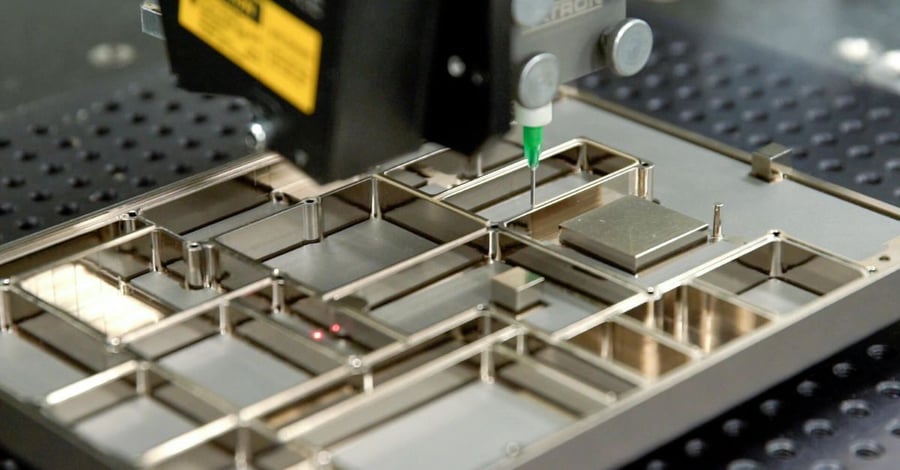
A form-in-place EMI gasket starts as a liquid. A CNC dispensing machine applies it directly onto the housing along a pre-programmed dispense path, following the exact geometry of the part. It then cures through heat, moisture, or UV exposure depending on the material, and bonds to the surface. The result is a gasket integrated into the housing rather than installed on top of it.
That distinction matters more than it sounds. Die-cut gaskets are manufactured separately, then assembled to the part. They rely on compression and fit to maintain position. FIP gaskets are formed to the part. There's no installation step, no risk of misalignment, and no gap between the gasket and the surface it's supposed to seal.
For drone communications enclosures, which frequently involve multi-compartment housings, narrow wall sections, and complex dispense paths with tight bend radii, that's not a minor advantage. It's often the only practical path to a manufacturable, repeatable seal.
What Makes a FIP Gasket Ruggedized?
"Ruggedized" gets used loosely. For a form-in-place EMI gasket, it has a specific meaning that goes well beyond shielding effectiveness numbers on a datasheet.
A ruggedized FIP gasket has to maintain its seal and its shielding performance across the full operating envelope of the platform. Not just at room temperature on a lab bench. That means surviving temperature cycling across the military operating range (-55°C to +125°C / -67°F to +257°F), resisting delamination under continuous broadband vibration, and retaining its mechanical and electrical properties after repeated compression cycles.
Environmental sealing is part of the ruggedized equation too. Dust, moisture ingress, salt fog, and condensation all threaten sensitive electronics in field-deployed systems. A conductive silicone FIP gasket that achieves >100 dB shielding effectiveness but fails its IP-rated seal after 500 hours of salt fog exposure isn't a ruggedized gasket.
The three dimensions that actually define ruggedization for FIP:
- Mechanical durability: Vibration resistance, compression set, substrate adhesion strength, and delamination resistance under shock and thermal cycling
- Environmental sealing: IP rating achievable through seal geometry, material shore hardness, and compression load. Dust and moisture protection sustained across the service life
- Chemical resistance: Compatibility with the specific chemical exposure profile of the platform. Including jet fuel, hydraulic fluid, cleaning solvents, and salt atmosphere where applicable
Standard commercial FIP materials can meet some of these requirements. Meeting all of them for a specific ruggedized application requires material selection to happen early, in parallel with enclosure design. Not after the housing geometry is locked.
Essential Background Reading:
- What Is a Form-in-Place Gasket: Core concepts behind FIP gasketing. How it works, where it's used, and why it differs from conventional gasket methods
- FIP EMI Gasket Design. Essential Considerations for Critical Electronics: The design fundamentals you need before specifying a form-in-place EMI gasket for a demanding application
- Custom Gasket Manufacturing, Cutting vs. FIP vs. Extrusions: A side-by-side comparison of gasket manufacturing methods to help you understand when FIP is and isn't the right choice
- Component Manufacturing for Unmanned Systems: How precision manufacturing requirements scale across drone platforms from Group 1 to Loyal Wingman class systems
FIP vs. Die-Cut: When the Geometry Makes the Decision
Die-cut gaskets make sense for large, flat sealing surfaces with simple perimeters and generous tolerances. When the enclosure geometry gets complex, the math changes quickly.
Consider a frequency-selective radar relay node with compartmentalized shielding between RF channels. Each compartment wall might be 1.5 mm to 2 mm wide. A die-cut gasket at that width is fragile, difficult to align, and nearly impossible to install without tearing or distortion. FIP dispenses directly onto the wall. Bead widths well under 1 mm are achievable, and cures in place with no handling risk.
| Factor | FIP Gasket | Die-Cut Gasket | Fabric-Over-Foam | Extruded Profile |
|---|---|---|---|---|
| Complex or narrow geometry | Handles intricate paths, narrow walls | Practical lower limit ~3. 4 mm width | Limited by foam thickness | Fixed cross-section only |
| Assembly labor | None. Dispensed and cured in place | Requires installation step | Requires installation step | Requires installation step |
| Alignment risk | Eliminated by fixturing and CNC path | Present at every assembly | Present at every assembly | Present at every assembly |
| Sealing consistency | Conforms to housing surface variation | Depends on compression and flatness | Depends on compression | Depends on groove fit |
| Combined EMI + environmental seal | Single bead, single material | Usually requires two separate solutions | EMI + environmental possible | Material-dependent |
| Minimum feature size | Sub-millimeter bead achievable | Limited by die punch geometry | Limited by foam cell structure | Limited by extrusion tooling |
| Tooling cost | No hard tooling required | Die tooling required per geometry | Carrier tooling required | Extrusion tooling required |
| Ruggedized environment fit | High, bonded, sealed, geometry-conforming | Moderate, relies on compression | Lower, foam degrades under cycling | Moderate. Depends on material |
Die-cut parts have real advantages: lower unit cost at volume, faster cycle time for simple geometries, no cure step. The right answer depends on the part. For most miniaturized UAV communications enclosures, FIP wins on geometry alone before environmental performance even enters the conversation.
Combined Function: EMI Shielding and Environmental Sealing in One Bead
This is where FIP earns its place on ruggedized platforms. A single dispensed bead can simultaneously achieve EMI shielding effectiveness and IP-rated environmental sealing. One gasket, one interface, one vendor.
Conductive FIP material (typically silicone elastomers loaded with silver, silver-copper, silver-aluminum, nickel-graphite, or silver-nickel particles) provide shielding effectiveness that can exceed 100 dB across frequencies from 200 MHz to 18 GHz.
Non-conductive FIP silicones handle the environmental sealing side: dust, moisture, and contaminant protection. For UAV platforms where the threat is primarily environmental rather than EMI, non-conductive FIP simplifies material selection while still delivering the geometry and adhesion advantages.
The real value on communications platforms is usually the combination. A drone relay node needs both: a conductive gasket for EMI, a foam tape or o-ring for environmental. This means two interfaces to manage, two installation steps, and two potential failure modes in the field. FIP collapses that into one.
Related Content:
- FIP EMI Gaskets. Precision Shielding for Complex Geometries: How form-in-place dispensing handles the multi-compartment enclosures and tight geometries that defeat die-cut solutions
- Conductive Fabric Gasket and Fabric-Over-Foam. Construction, Performance, and Application: How fabric-over-foam gaskets are built and where they fit versus FIP in ruggedized electronics applications
- Drone EMI Shielding for UAV Payloads. FIP Gaskets, SWaP Constraints, and GPS Protection: How SWaP-driven design constraints interact with EMI shielding requirements on miniaturized UAV payloads
- Robotic Gasket Dispensing. 6 Applications for Form-in-Place Gaskets: Real-world applications where robotic FIP dispensing outperforms manual or die-cut gasket methods
- Selecting the Right RF Gasket Material for Defense Applications: A practical framework for matching conductive elastomer filler systems to military operating environment requirements
Material Selection for Harsh UAV Environments
Choosing the right FIP material for a UAV communications build requires thinking through the full operating envelope, not just peak shielding performance. Drone platforms expose gaskets to conditions that surface failures quickly.
Vibration and Shock
UAV platforms, particularly rotary-wing systems all generate continuous broadband vibration throughout operation. Fixed-wing surveillance platforms add launch and recovery shock loads to the profile. Silicone-based FIP materials handle this well. Silicone's inherent flexibility and strong substrate adhesion prevent the delamination and compression set that rigid or poorly bonded materials develop over time.
Temperature Range
Tactical drones operate across extreme temperature swings: high-altitude cold soak followed by direct sun heating on the ground, or engine proximity heat on fixed-wing platforms. Nolato TriShield materials are rated from -55°C to +125°C (-67°F to +257°F), which covers most military and commercial UAV operating envelopes. Confirm that your material selection holds its shielding effectiveness and mechanical properties across that full range. Not just at room temperature.
Jet Fuel and Chemical Resistance
Fixed-wing UAVs that use aviation fuel or jet fuel introduce a chemical exposure risk that rotary-wing designers don't typically face. Fuel vapor permeates enclosures. Fuel contact occurs during servicing. Standard silicone FIP materials aren't rated for jet fuel resistance.
Fluorosilicone FIP formulations are the answer when fuel or hydraulic fluid exposure is part of the operating profile. Fluorosilicone maintains its mechanical properties and seal integrity in the presence of JP-8, Jet-A, and common hydraulic fluids where standard silicone would swell and lose adhesion. This is a material selection decision that has to happen early. Fluorosilicone narrows the candidate list and may require adjustment to groove geometry and dispense path parameters. Engage with a materials engineer before locking in your enclosure design.
Galvanic Corrosion at the Gasket-Substrate Interface
This failure mode gets less attention than it deserves. Conductive FIP materials contain metallic filler particles, silver, nickel, copper, and those particles are in direct contact with the housing substrate. When dissimilar metals contact each other in the presence of moisture, galvanic corrosion accelerates.
For defense and aerospace applications using machined aluminum or magnesium housings, filler selection matters beyond shielding effectiveness. Silver-nickel and nickel-graphite filler systems are generally better choices for aluminum substrates than bare silver or silver-copper, which can drive galvanic attack in humid or salt-fog environments. Confirm substrate compatibility with your materials engineer, particularly for coastal or maritime operations.
| Environmental Challenge | Key Material Consideration |
|---|---|
| Continuous vibration (rotary-wing) | Silicone base, strong substrate adhesion, low compression set |
| Thermal cycling (-55°C to +125°C) | Full-range property retention, not just room-temp spec |
| Jet fuel / hydraulic fluid exposure (fixed-wing) | Fluorosilicone FIP formulation required. Standard silicone does not qualify |
| High humidity / condensation | Non-conductive or conductive silicone FIP, IP-rated seal geometry |
| UV exposure | UV-stable formulations or protected installation |
| Salt fog / coastal operations | Galvanic-compatible filler (Ag/Ni, Ni/C vs. bare silver); corrosion-resistant plating on substrate |
Next Steps:
- Form-in-Place Gasket Guide: The complete engineering reference for FIP gasket design, material selection, dispensing, and production. Over 6,500 words of detailed guidance
- Mastering FIP Gasket Design. A Comprehensive Guide: Advanced design guidance covering groove geometry, dispense path optimization, tolerance management, and DFM best practices
- Four Keys to Successful Form-in-Place Gasket Design: The most important design decisions that determine whether a FIP gasket performs reliably in production
- Critical FIP Gasket Features Every Design Engineer Should Know: Feature-level design details, groove dimensions, wall widths, compression targets. That directly affect gasket quality
- FIP Gasket Services. What to Look for in a Manufacturing Partner: How to evaluate FIP dispensing partners on quality systems, engineering depth, and program support capabilities
MIL-DTL-83528 and Ruggedized FIP Gaskets
Defense programs sourcing conductive elastomer gaskets frequently encounter MIL-DTL-83528, the military specification that defines performance requirements for conductive elastomers used in EMI shielding applications. Understanding how FIP materials map to this spec matters for program documentation and qualification.
MIL-DTL-83528 organizes conductive elastomers by type based on filler material and base elastomer. Type designations include silver-aluminum, silver-copper, silver-nickel, nickel-graphite, silver-glass, and others. Each with defined shielding effectiveness floors, volume resistivity limits, and environmental performance requirements.
FIP materials from major suppliers. Including Parker Chomerics CHO-FORM, Nolato TriShield, and Laird Performance Materials series. Are formulated to meet the shielding and environmental requirements that MIL-DTL-83528 types define. FIP materials are dispensed products, not molded sheet stock, and material qualification to a specific MIL-DTL-83528 type requires documentation from the material manufacturer.
For programs requiring MIL-spec traceability, confirm the following with your FIP dispensing partner:
- Which MIL-DTL-83528 type the specified material is qualified to, per manufacturer documentation
- Whether the dispensed gasket geometry affects qualification applicability
- What material certifications and certificates of conformance will ship with the finished parts

Design Considerations That Affect Manufacturability
FIP is precise, but it isn't forgiving of late-stage design decisions. Getting the enclosure geometry right before dispensing starts is the difference between a first-article pass and an expensive rework loop.
Groove geometry matters. A defined groove that constrains the bead laterally gives you more consistent height and width. Critical for managing compression during assembly. Without a groove, you're relying entirely on bead consistency and mating surface parallelism.
Start and stop zones need attention. Every dispense path has initiation and termination points. Standard bead tolerances of ±0.15 mm (±0.006") apply across most of the path. In the zones around starts, stops, and T-joints, height and width variation can reach -30% to +45% from nominal. Design your sealing interface to tolerate this, or locate start/stop points at non-critical geometry.
Minimize T-stops and crossing paths. T-joints are where one dispense path meets another. The last point of one bead, the first point of the next. Each T-stop is a potential void or bead discontinuity. Design the dispense path to minimize T-stops, route crossings, and direction reversals. A dispense path designed for FIP manufacturability will have fewer T-stops and longer uninterrupted runs. This is a DFM conversation that costs nothing to have before the design is released.
Narrow walls push process limits. FIP bead widths can be very small. Modus has developed custom solutions for bead sizes below standard material specifications, but narrow walls raise alignment and overflow risk. Share the full housing drawing with the dispensing engineer before the design is released. Problems caught in DFM cost nothing. Problems caught at first article cost weeks.
See It In Action:
- UAV Payload Integration. Precision Manufacturing for Small UAV Systems: How precision manufacturing requirements translate to real hardware on small UAV payload programs
- Counter-UAS Systems. Inside the Hardware That Makes cUAS Components Work: The component-level manufacturing requirements behind counter-drone systems where reliability is mission-critical
- The DoD Replicator Initiative. What Attritable Drones Demand from the Defense Supply Chain: How the push for mass-producible attritable drones is reshaping manufacturing requirements across the defense supply chain
- EMI Shielding in Defense and Aerospace. CHO-FORM Material Selection Guide: A detailed look at how CHO-FORM FIP materials are selected for defense and aerospace EMI shielding programs
The Case for Vertical Integration on UAV Communications Builds
A UAV communications housing doesn't arrive at FIP dispensing ready to go. It starts as raw material or a casting, gets machined to tolerance, typically gets plated or coated for conductivity and corrosion resistance, then reaches the dispenser. After FIP, thermal interface materials or absorbers may be added before final assembly.
That's four or five process steps. If each step lives at a separate vendor, you're managing four or five sets of drawings, lead times, shipping logistics, and quality handoffs. Every handoff is a chance for miscommunication, a compliance gap, or a schedule slip.
Vertical integration under one roof. Machining, plating and coating, FIP dispensing, thermal material assembly. Compresses that into a single workflow. One purchase order. One quality system. One set of hands on your CUI.
For programs operating under ITAR requirements or CMMC compliance obligations, that last point is significant. Every vendor in the supply chain that touches controlled technical data is a compliance verification burden. Fewer vendors means less exposure and simpler audits.
Modus Advanced holds CMMC Level 2 certification, validated through third-party C3PAO assessment, with all 110 NIST SP 800-171 controls implemented. ITAR registration and AS9100 certification cover the full manufacturing scope. Machining through FIP dispensing through assembly. No competitor in this space combines CMMC Level 2, ITAR, and AS9100 across a vertically integrated FIP operation. Your drawings stay in one place, processed by one team, under one audited quality system.
Frequently Asked Questions About Form-in-Place EMI Gaskets
What is a form-in-place EMI gasket?
A form-in-place EMI gasket is a conductive elastomer gasket dispensed as a liquid onto a housing using CNC-controlled robotic equipment. The material, typically a silicone elastomer loaded with conductive filler particles such as silver, silver-copper, silver-nickel, or nickel-graphite. Follows a pre-programmed dispense path and then cures in place. The result is a gasket bonded to the housing surface that conforms precisely to its geometry. FIP gaskets can achieve shielding effectiveness exceeding 100 dB across 200 MHz to 18 GHz, with bead tolerances of ±0.15 mm (±0.006").
When should I use FIP instead of a cut or molded gasket?
FIP is the right choice when the housing geometry is too complex, too narrow, or too intricate for die-cut or molded gaskets to seal reliably. It's also preferred when you need a gasket bonded and integrated into the housing rather than installed as a separate component. Eliminating alignment error and installation labor. Multi-compartment enclosures, wall widths under 3. 4 mm, and applications requiring combined EMI and environmental sealing in a single bead are strong candidates for FIP.
What shielding effectiveness can FIP gaskets achieve?
Conductive FIP materials typically achieve shielding effectiveness greater than 90. 110 dB across frequencies from 200 MHz to 18 GHz. Higher-performance materials achieve more: Nolato TriShield 8813 achieves average shielding effectiveness of 130 dB from 0.3 to 20 GHz on aluminum substrates. Actual performance depends on filler material, filler loading, gasket geometry, substrate conductivity, and compression load at the interface.
What conductive fillers are used in ruggedized EMI gaskets?
Common conductive fillers in ruggedized FIP EMI gaskets include silver-aluminum, silver-copper, silver-nickel, and nickel-graphite. Filler selection affects shielding effectiveness, volume resistivity, galvanic compatibility with the housing substrate, and cost. For aluminum or magnesium housings in corrosive environments, silver-nickel and nickel-graphite fillers are generally preferred over bare silver or silver-copper to reduce galvanic corrosion risk.
Can FIP gaskets meet MIL-DTL-83528 requirements?
FIP materials from major manufacturers are formulated to meet the shielding effectiveness and environmental performance requirements that MIL-DTL-83528 type designations define. Qualification traceability requires material certification documentation from the manufacturer. Confirm which MIL-DTL-83528 type applies to your specified material, and verify that your FIP dispensing partner can provide certificates of conformance with finished parts.
Is fluorosilicone required for aerospace FIP applications?
Fluorosilicone is required when the operating environment includes exposure to jet fuel, aviation fuel, hydraulic fluid, or other petroleum-based fluids. Standard silicone FIP materials aren't compatible with these exposures. They will swell and lose adhesion. For fixed-wing UAVs and aircraft electronics where fuel or hydraulic fluid contact is possible, fluorosilicone FIP formulations are the correct specification. This choice must happen early in the design process, as fluorosilicone materials may affect groove geometry and dispense path design.
What tolerances can FIP dispensing hold?
Standard FIP bead tolerances are ±0.15 mm (±0.006") for width and height across most of the dispense path. Some materials hold tighter tolerances: Nolato TriShield materials achieve ±0.10 mm for gaskets under 1 mm height. Near dispense path starts, stops, and T-joints, variation can be higher. Typically -30% to +45% from nominal within approximately 3 mm of these features. Design the sealing interface to accommodate this, or position start/stop points at non-critical geometry.
How does FIP gasketing reduce assembly cost?
FIP eliminates the installation step required for separate gaskets. The gasket is dispensed and cured directly onto the housing, so it arrives at your assembly line ready to close. No alignment, no adhesive application, no risk of installation-induced damage. For complex geometries where manual gasket installation is difficult or unreliable, FIP also reduces rework and scrap. Material cost comparisons with die-cut gaskets aren't apples-to-apples: FIP material cost includes dispensing, but the resulting reduction in assembly labor should be factored into the total cost model.
Built for the Mission, Not the Spec Sheet
The engineer building a drone communications subsystem isn't designing a gasket. They're trying to close out an enclosure that has to work in conditions that most commercial hardware was never designed for.
Form-in-place EMI gaskets give you the geometry freedom to seal complex housings that die-cut parts can't reach. They give you combined EMI and environmental performance in a single bead. And they give you a dispensed-in-place, bonded interface that holds up to vibration and shock loads that would dislodge a pressed-in gasket over time.
Material selection is where the work happens. Matching the silicone or fluorosilicone formulation and filler system to the actual operating envelope of the platform. That conversation is easier when the people dispensing the gasket are also the people who machined the housing and specified the plating. That's what vertical integration actually means in practice.
When the relay node has to hold its seal through a combat deployment, the pilot depending on that communications link doesn't care about your supplier count. One day matters. Let's solve this.